
-
-
Before commissioning, please make sure ALL of the following steps have been completed, before continuing!
-
Machine Assembly. ALL steps listed at the bottom of this page must be followed, in roughly the order shown.
-
Install Pronterface / Printrun.
-
Install the Marlin firmware into the Arduino Mega 2560.
-
NOTE: We're currently in the process of transitioning from Marlin to FireStep on the Arduino, for motion control. This guide is currently written for Marlin, but will soon be re-written for FireStep.
-
-
-
This guide will make heavy use of g-code (the protocol between the host software and the motion controller). We are communicating to the motion controller with these low-level commands, which gives us a bit more power and flexibility during the commissioning phase.
-
A g-code summary has been created, and is located on FirePick Delta's documentation page: http://delta.firepick.org/g-code-referen...
-
Please refer to this reference if you need to do any extended troubleshooting, or are interested in expanding or modifying FPD commands.
-
-
-
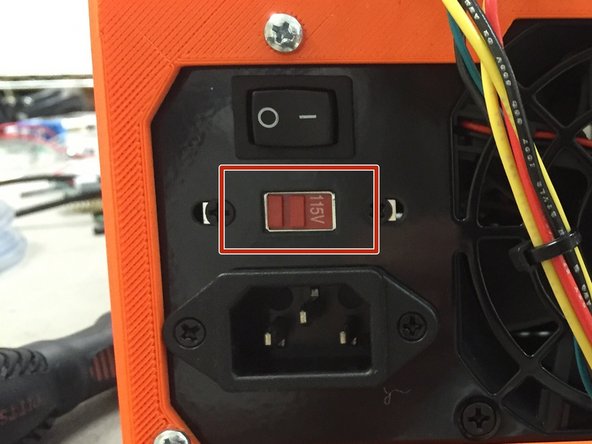
Warning: Failure to do this step may cause bad things to happen!
-
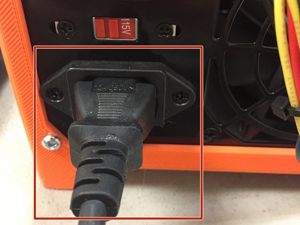
If your household power uses 115V, set the ATX power supply switch to the 115V positon.
-
If your household power uses 230V, set the ATX power supply switch to the 230V positon.
-
-
-
Sanity checks before continuing:
-
Check for loose screws. Tighten everything.
-
Orientation of the end effector. The camera should be in the FRONT of the machine. The fan can be mounted on either side.
-
-
-
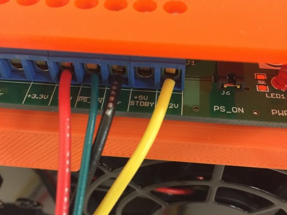
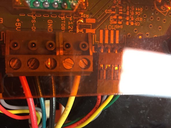
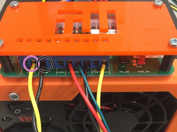
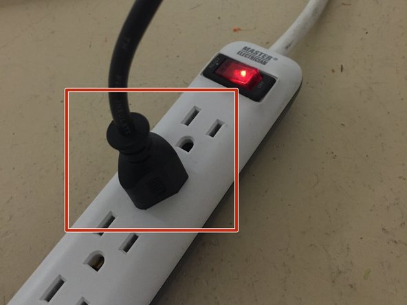
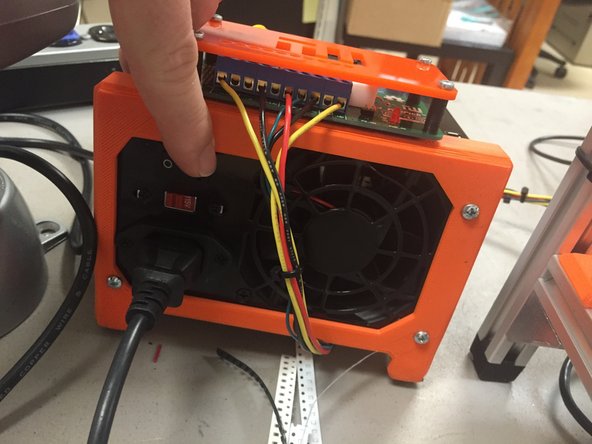
Ensure that the ATX power supply power connections are made as shown in the first image.
-
The other side of those wires should connect to the EMC02 motion controller. The wires should be cable-tied to the frame, and clear of any moving parts.
-
-
-
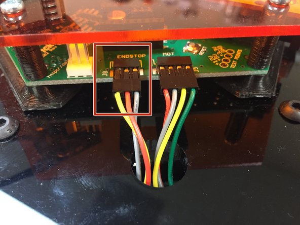
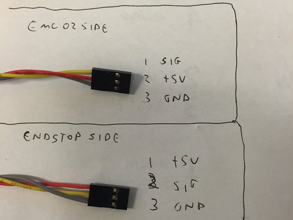
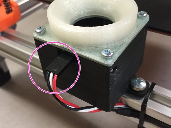
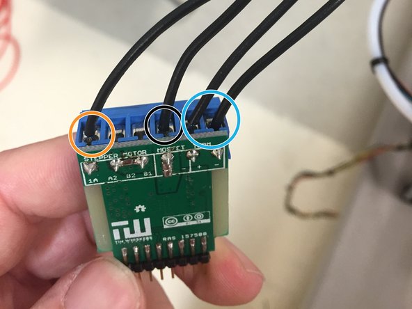
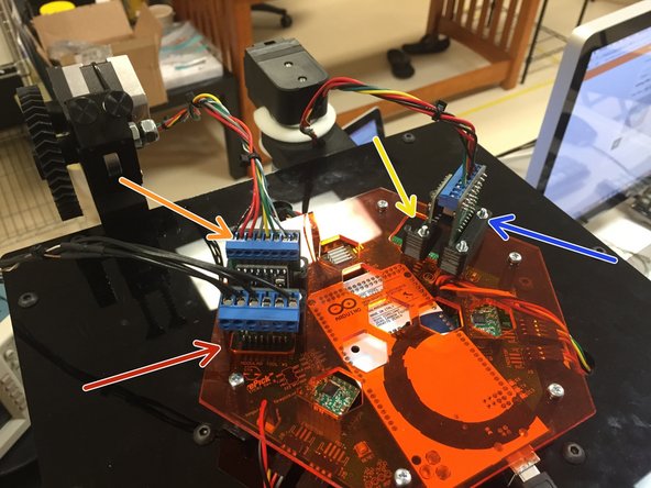
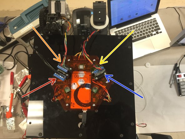
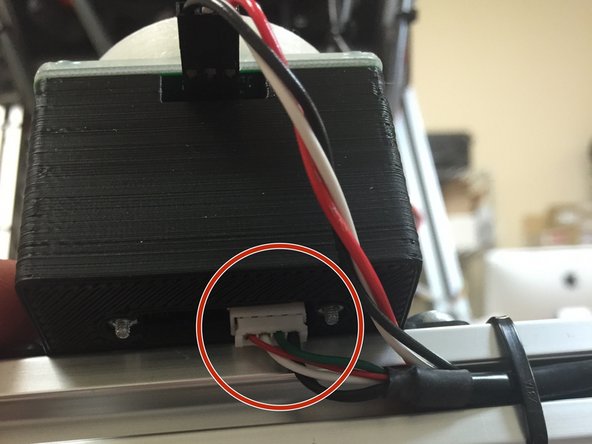
Ensure that the limit switch and motor cable wiring are as shown in these pictures.
-
Pay special attention to wire color and order. Ensure it's exactly the same for your machine, for all three limit switches and all three motors.
-
-
-
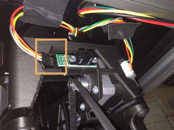
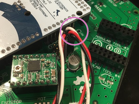
Observe the orientation shown on the pictures, including the wire color order. Make 100% sure your wiring matches the pictures.
-
-
-
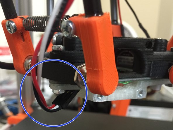
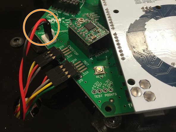
Observe the orientation shown on the pictures, including the wire color order. Make 100% sure your wiring matches the pictures.
-
Note that it's not 100% necessary at this point to have the up-looking camera built and installed. The up-looking camera board was provided in kit form to be used as a PnP SMT practice kit. Therefore, it's OK if you don't have it installed at this point,
-
-
-
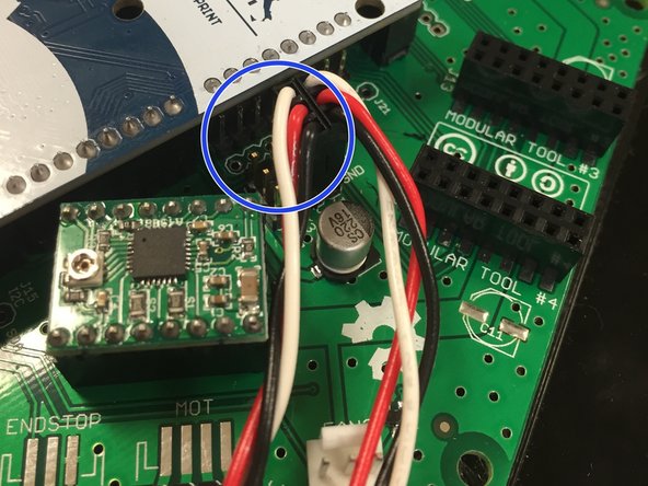
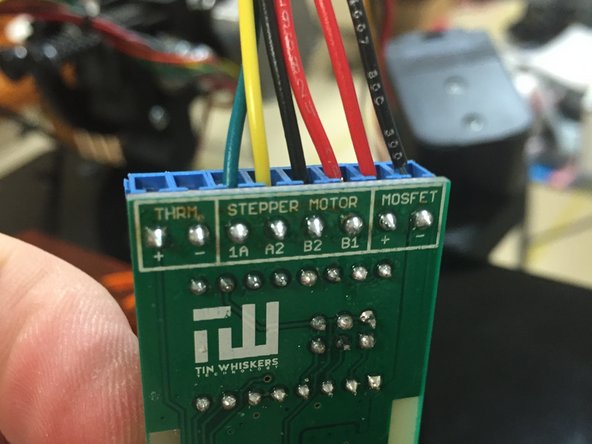
Observe the orientation shown on the pictures, including the wire color order. Make 100% sure your wiring matches the pictures.
-
-
-
Ensure that the SMT modular tool is connected as shown.
-
-
-
NOTE: Currently, the 3D printing modular tool must be plugged in for the Marlin firmware to work. Otherwise, it will think that the hotend thermistor is reading too high, and will shut off. I'm currently working on a build that doesn't have this logic, but the changes are widespread and will be a while before it's fully tested.
-
For now, if you're not using the 3D printing modular tool, simply wire a 100K ohm resistor into the terminal strip where the hotend thermistor would go.
-
The 3D printing modular tool PCB should look like the picture to the left. Please refer to the 3D printing modular tool instructions to ensure that it is wired properly.
-
(picture TBD..)
-
-
-
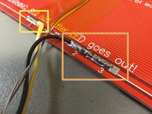
Double-check your wiring as shown. Refer to the heated bed guide for these connection points.
-
Note that the bullet point colors below correlate to the picture markers, not necessarily the wire color.
-
Heated Bed -
-
Pwr supply +12V
-
Pwr supply GND
-
Thermistor wiring
-
NOTE: For now, it is recommended to disable the heated bed while we verify its use under all corner cases. Disable it by disconnecting the yellow +12V wire from the ATX power supply.
-
-
-
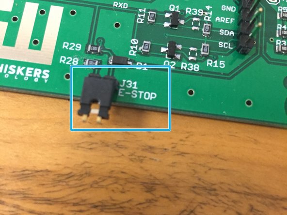
Ensure that either:
-
(A) A shunt / jumper is placed on the EMC02 E-stop header, or
-
(B) An actual e-stop switch is mounted and connected to this header. Note the switch is normally closed (not shown, not a part of a kit, rather this is provisioned for future expansion)
-
-
-
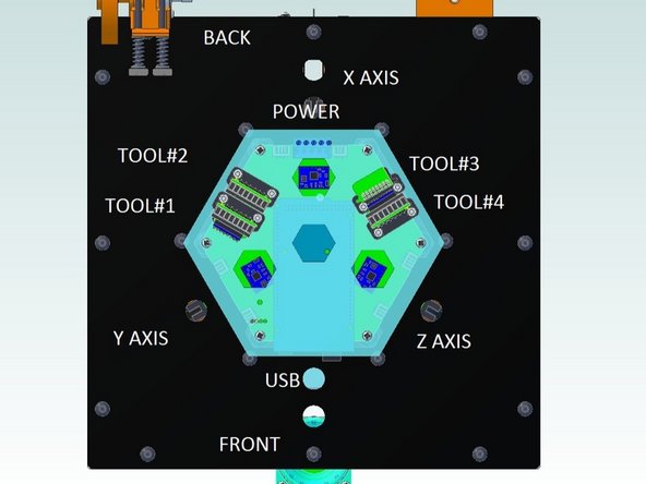
Plug in the modules as shown.
-
Tool 1: Heated Bed
-
Tool 2: 3D printing Hotend
-
Tool 3: (Empty)
-
Tool 4: PnP SMT pump and nozzle
-
-
-
Plug the USB cable into the bottom of the up-looking camera module, if you haven't already.
-
Plug the other end of the USB cable into your PC or laptop.
-
Use a web-cam viewing tool to see that the camera works.
-
-
-
Connect the USB down-looking camera to your PC or laptop. The other end of the USB cable should be soldered directly to the camera, as per the guide.
-
Use a web-cam viewing tool to see that the camera works.
-
-
-
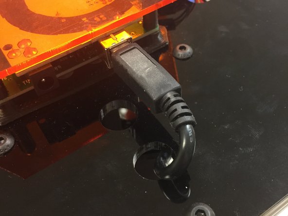
Connect the USB cable to the Arduino. It is advised to route the excess cable out the hole in the PC01 plate, and down the side of the machine.
-
Make sure that the cable does not interfere with the delta mechanism, i.e., make sure it is cable-tied out of the way of the delta arms.
-
Connect the other side of the USB cable to the host PC or laptop.
-
-
-
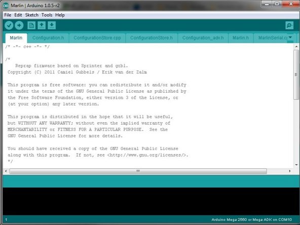
Program the Arduino if you haven't already.
-
This guide should be used to program the firmware. It includes which repo and which branch to run the firmware from.
-
-
-
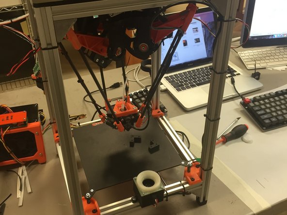
The delta mechanism is movable while it is powered down. This is normal.
-
Move the end effector to roughly center of the work area. This will ensure that nothing bad will happen during homing.
-
-
-
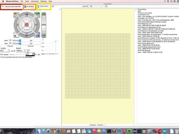
Launch Pronterface.
-
Select the COM port that the Arduino Mega is assigned to.
-
For baud rate, type in '250000'
-
Hit 'Connect'.
-
If this doesn't work, some common-sense troubleshooting will be needed. Ensure the Arduino is programmed properly. Ensure the USB port is connected and not in use by another app.
-
NOTE: We are only using Pronterface at this point for debugging. It's great because it gives us raw access to the motion controller so that we can troubleshoot and control the machine. Later, we'll run OpenPnP instead of Pronterface.
-
-
-
Send 'M80' in the pronterface input console. The red LED light on the FirePick Delta's ATX power supply board should light up after this command is entered.
-
Send 'M81' to pronterface. The LED should turn off.
-
Send 'M80' one more time to turn it back on.
-
Type 'M999' to reset any errors that happened while the power supply was off.
-
-
-
Each stepper driver module has a small trim potentiometer. This potentiometer sets the current drive to the motors.
-
This potentiometer setting should be a balance / compromise between:
-
High enough so that the stepper motor does not stall and lose steps
-
Low enough that the motor does not get hot to the touch (should not get past the threshold of pain, which is around 60 C or so)
-
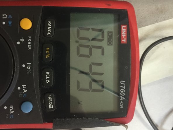
Currently, I have mine set to 0.65 volts. This value is subject to change. This page will be updated if / when this value changes.
-
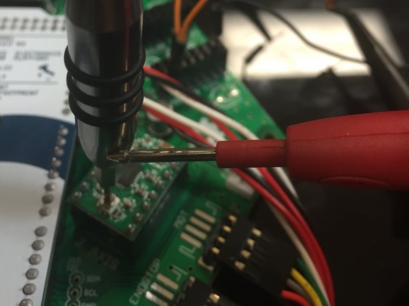
To adjust the trim pot, use a metal 1.5mm wide flat-head screwdriver, and place the DMM positive lead on the screwdriver. Place the negative lead on GND
-
NOTE: The standard tip of most multimeters will fit snugly in the ATX power supply's spare Molex 4-pin connectors. It is recommended to put the black DMM tip here, in the center two positons.
-
-
-
Type 'M119' in Pronterface.
-
It should return:
-
x_min: open
-
y_min: open
-
z_min: open
-
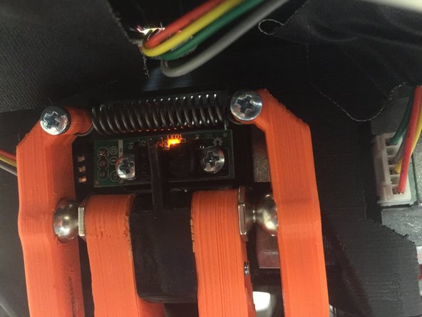
Manually move the delta mechanism so that the "X" arm is touching the optical sensor. The amber LED should turn on. Type M119 again, and Marlin should report that the X optical switch is closed.
-
Repeat this for the other two axes.
-
Do not continue until all three homing switches work properly. Troubleshoot as needed if they are not working correctly. If you try to home without these switches working, the homing function will crash and could cause damage.
-
-
-
Ensure that the delta mechanism is roughly centered near X=0, Y=0.
-
Click the 'Home all Axes' or type in G28.
-
← Watch the video for an example.
-
The delta mechanism should move all arms up to the endstops, and once the first one trips, it should sequentially home each one. It should look like the video in the left image area.
-
-
-
NOTE: Currently skipping this until Marlin firmware changes are complete
-
-
-
NOTE: Currently skipping this until Marlin firmware changes are complete
-
-
-
Type 'G0E90F1000'. Check to see that the SMT nozzle moves exactly 90 degrees.
-
← Watch the video for an example.
-
TODO: Check rotation. Clockwise or counter-clockwise for positive increments?
-
-
-
Type 'M4'. Verify that the vacuum pump turns on (it's really loud and hard to miss).
-
← Watch the video for an example.
-
Type 'M5'. Verify that the vacuum pump turns off.
-
-
-
Type 'M421R255'. Check to see that the up-looking camera LED light turns on.
-
Type 'M421R0'. Check to see that the up-looking camera LED light turns off.
-
Note that it's not 100% necessary at this point to have the up-looking camera built and installed. The up-looking camera board was provided in kit form to be used as a PnP SMT practice kit.
-
-
-
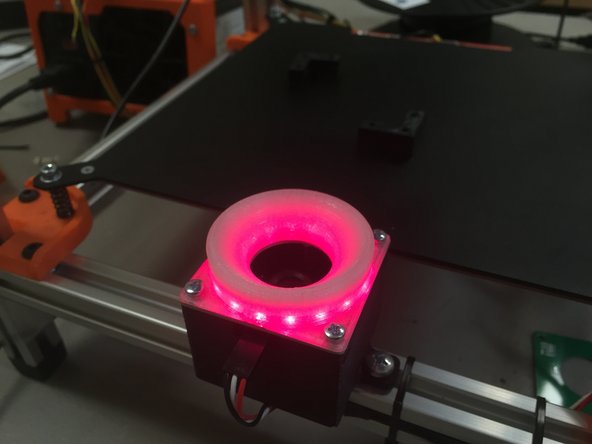
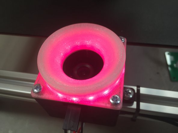
Type 'M420R255'. Check to see that the down-looking camera lights up.
-
Type 'M420R0'. Check to see that the down-looking camera light turns off.
-
-
-
Your machine is now commissioned. You may now run the Eclipse Setup / OpenPnP tutorial.
-

Cancel: I did not complete this guide.
3 other people completed this guide.

3 Comments
Reef, per my email on the dev list, M80/81 are not backwards (although if an older firmware version is loaded, it will appear this way). Mostly replying here for others that might have the same issue... best action to take is to do a git pull using the specified Marlin fork and branch, to main/latest, and try the commissioning steps again.. that should fix the M80/81 problem.