
-
-
Ensure that you've completed the Modular SMT Tool guide, and the Vacuum pump mount assembly.
-
-
-
A problem was discovered that the T-slot extrusion nuts we chose were so thick that they interfered with the 3D printed mount's anti-rotation boss.
-
The kits that got shipped to beta test customers need to be modified in order to fit properly on the frame. This is quick and easy to do with a high-speed rotary (Dremel et. al.) tool.
-
Shave of a few millimeters of the raised portion, just around the 5.5mm hole.
-
The part on the left is un-modified. The part on the right is modified.
-
-
-
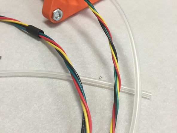
Wires should have been twisted when the modular tool / NEMA 8 motor assembly was being built. Ensure the wires are still tightly twisted.
-
-
-
Thread the stepper motor wires through the hole in the 3DAT0005 mount (from the bottom, out the top).
-
Aim for about 230mm (~9") of wire out the top.
-
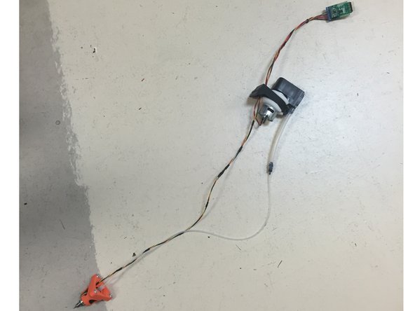
Next, thread the vacuum pump wires through in the same fashion. Get both sets of wires to line up at the ends, and remove any slack in the wires.
-
Use a cable tie at the mount to hold the wires in place at that position.
-
Ensure the wires and assemblies now look like the pictures to the left.
-
Connect the small silicone tube to the barbed fitting, if you haven't done so already.
-
-
-
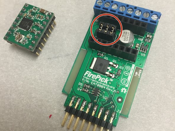
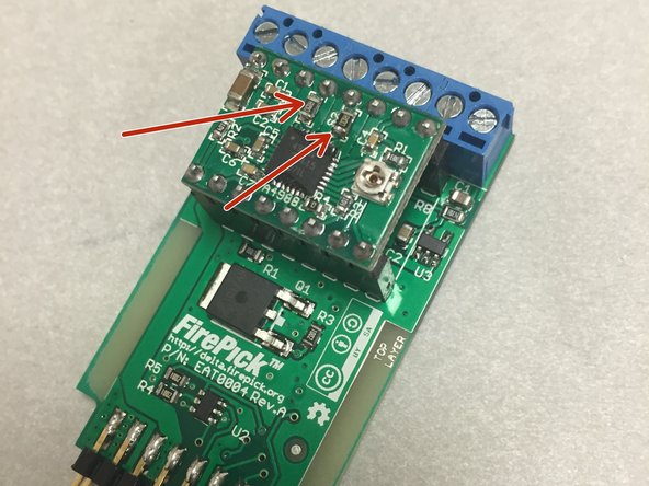
Locate the EAT0004 PCB. Look it over visually and make sure we didn't miss anything.
-
Ensure that the three jumpers (shunts) are placed on the PCB, as shown in the picture. These set the micro-stepping ratio on the stepper driver.
-
Locate the StepStick stepper driver module. Visually inspect it and look for any damage or defects.
-
-
-
Plug in the StepStick module. Ensure that you are placing the module on with the correct orientation. The two big resistors (S1 and S2) should face the blue terminal block. These are the sense resistors and are located near the stepper motor pins.
-
-
-
Strip the ends of the stepper motor wires and the vacuum pump wires, if not already done. Do not tin the wires.
-
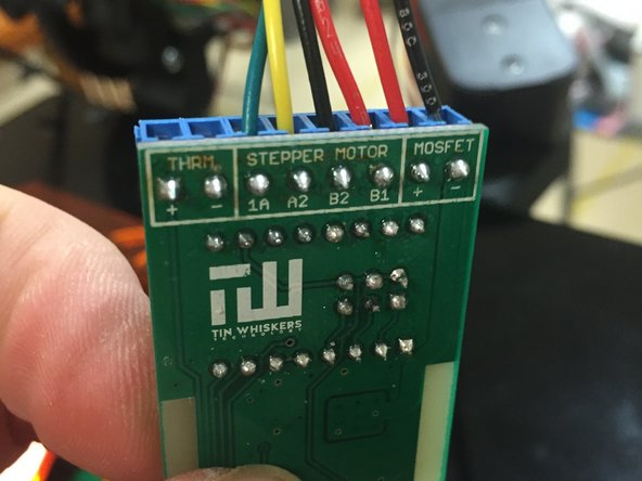
Insert the stepper motors into the middle four terminals, as shown.
-
Green - A1
-
Yellow - A2
-
Black/Gray - B2
-
Red - B1
-
Insert the vacuum pump wires into the MOSFET terminals. Insert RED into the "+" terminal and BLACK into the "-" terminal.
-
Tighten down on the screw terminals and ensure that the wires do not pull out.
-
-
-
Attach pump Mount to machine frame, using a M5 x 10mm button-head cap screw.
-
-
-
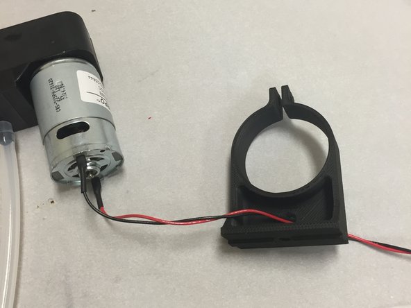
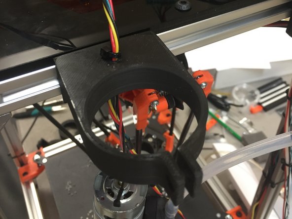
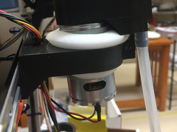
Locate the vacuum pump into the mount, as shown.
-
Note that the black and red wires may have to slip through the clamp area, in order to orient the pump correctly in the mount.
-
-
-
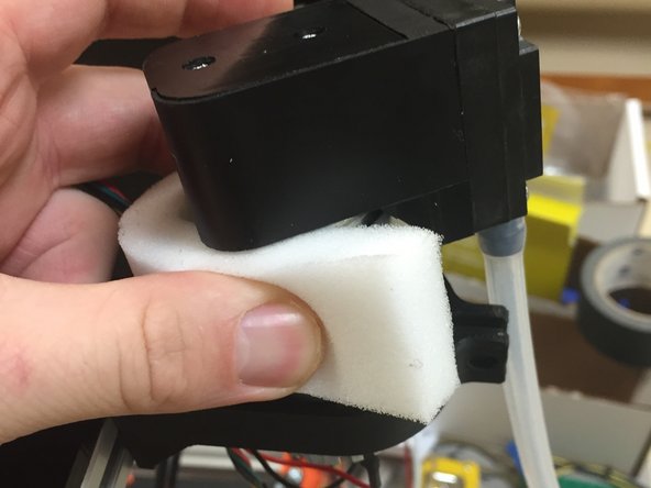
Wrap the piece of foam around the pump motor.
-
NOTE: This foam will act as a vibration damper, when the pump is running. It is rather noisy and shaky while it's on.
-
-
-
Carefully try to compress the foam and slide it down so that it comes out the bottom of the mount.
-
Be extremely careful not to bend the 3D printed mount, as it might break.
-
-
-
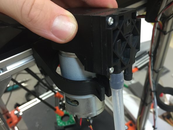
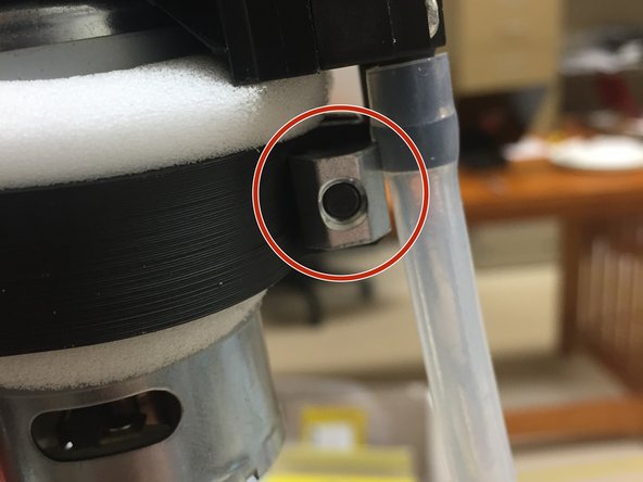
Add an M5 x 14mm screw through the clamp.
-
Use an M5 extrusion nut on the other side to secure it.
-
NOTE: Do not over-tighten. Tighten it only enough to ever so slightly compress the foam. Check this screw from time to time to ensure the tension is correct.
-
NOTE: The fastener in this step is normally a pan-head machine screw, but a button head cap screw is shown. Technically either will work, but the kits shipped pan-heads.
-
-
-
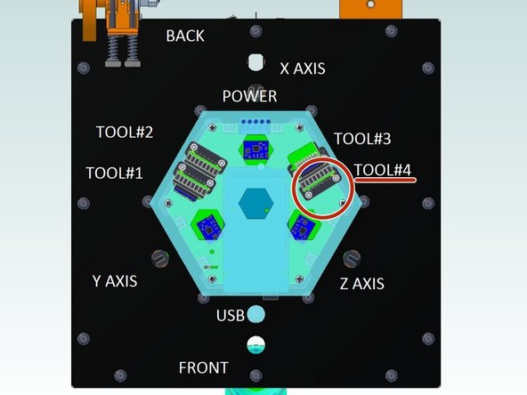
Plug the module into the EMC02 as shown.
-
Currently, it must be plugged into Slot #4 as shown. This is a software issue that we're working on; eventually these modules will be auto-sensing and hot-pluggable, but for now, it's hard-coded to work in slot #4.
-
-
-
Insert the Modular tool, as shown.
-
Looks like Dozuki isn't handling the video meta-data correctly on the preview image... Do not turn your machine sideways!
My end did not fit anywhere near this smoothly, required serious work with the dremel and utility knife to get it to snap in and out fully.
Anthony Webb - Resolved on Release Reply
-
-
-
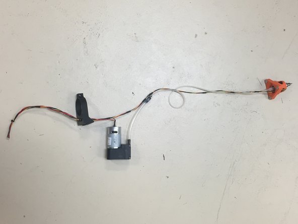
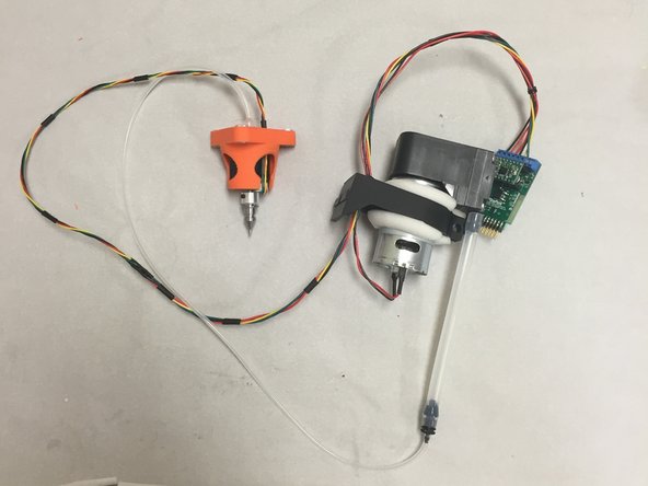
The wiring is now complete. Your tool should be mounted on the machine and ready to go (shown below off the machine, for illustration purposes)
-
During the commisioning process, you will need to dial the stepper driver potentiometer, which sets the stepper drive current. This will be covered in the commissioning guide.
-


Cancel: I did not complete this guide.
5 other people completed this guide.
