
Tools
No tools specified.
Parts
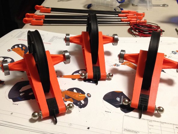
- 3D0001a - Delta motor Assembly - 608 bearing block × 6
- 3D0002b - Delta motor assembly - Pulley (150T) × 3
- 3D0003a - Delta motor assembly - Delta arm 90mm × 6
- 3D0003b - Delta motor assembly - Delta arm 90mm nut × 6
- 3D0004 - Delta motor Assembly - 608 bearing block caps × 6
- "Delta Mechanism Hardware Set" bag
-
-
You will use the hardware bag labeled "Delta Mechanism Hardware Set"
-
-
-
Insert two M5 x 20mm button-head cap screws into each 3D0001a 608 bearing block.
-
Insert two M3 x 20L screw into each 3D0004 bearing block cap
-
NOTE:Do not attach bearing cap to upper arm part at this time
-
-
-
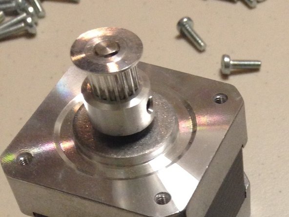
Attach the DGP16T pulley (GT2, 16-tooth) onto the 5mm stepper shaft.
-
Find the two M3 x 6L set screws and thread them into the pulley set screw holes. Note that these may already be in the pulley if you purchased the beta kit from us.
-
NOTE: Do not worry about exact alignment at this point. This will be set at the time that the GT2 belts are installed.
-
Tighten both set screws (just enough to keep the pulley from coming loose)
-
-
-
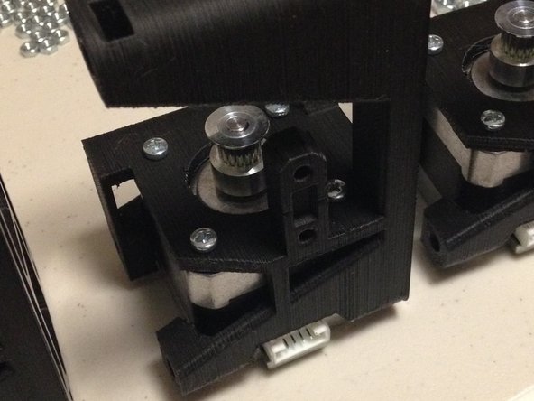
Insert stepper motor into 3D00456c stepper bracket, ensuring that the stepper motor electrical connector is positioned on the correct side, as shown.
-
Attach with 4x M3 x 8mm screws. NOTE: Your kit may have shipped with M3x12 screws in place of M3x8. Screws longer than M3x8 may bottom out inside the stepper motor. You may use M3x8's purchased locally or obtained through TWT, or use M3 washers and/or M3 nuts to prevent the M3x12's from bottoming out.
-
Tighten all screws
-
-
-
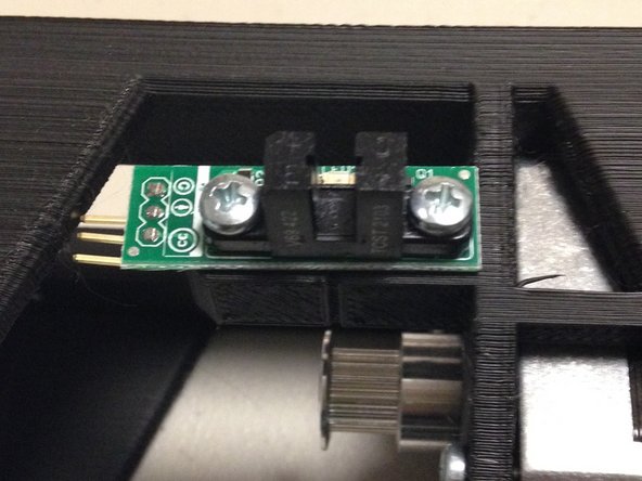
Insert 2x M3 x 20L screws through the PCB, and into the 3D printed bracket. Note the orientation, with the connector on the left, away from the motor.
-
Secure with 2x M3 nuts from the back side.
-
-
-
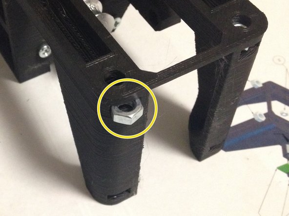
Insert M5 nut into top and bottom corners of frame.
-
NOTE: some nuts may fall out if the hole is large; keep a close eye for errant parts laying around
-
-
-
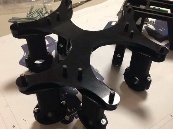
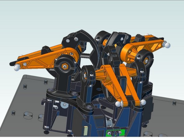
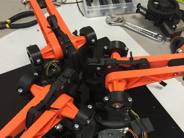
Attach delta arm mechanism to acrylic delta motor plate using M5 x 20mm button-head cap screws
-
NOTE: Despite what the picture shows, do not attach bearing blocks to the delta arm mechanism.
-
-
-
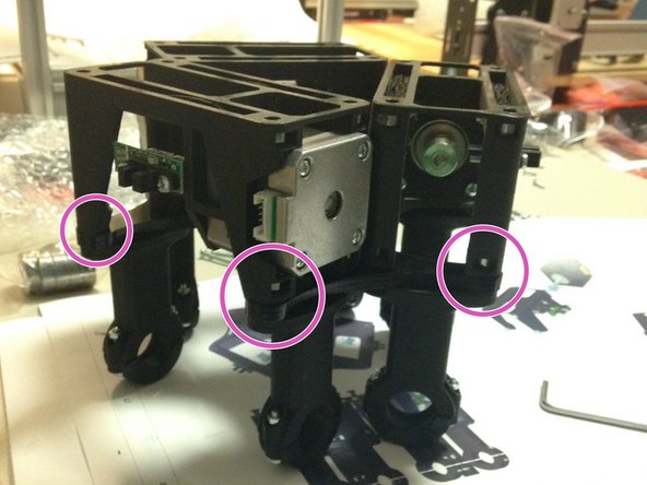
Place 3x 3D00456c stepper brackets onto top of the PC03 delta motor plate.
-
Screw M5 button-head cap screws into stepper brackets, using nuts previously inserted.
-
Tighten all fasteners.
-
IMPORTANT: The opto end stops mounted on the stepper brackets all face OUTWARD, and the open side of the stepper brackets face the bearing blocks.
-
-
-
Attach motor plate to top plate using M5 x 14L button-head cap screws and M5 nuts previously inserted in to the stepper mount.
-
Tighten the screws until just snug, then tighten 1/8 of a turn past that. There's no need to go tighter - the top plate is made of acrylic which can crack if "squished" too much by the metal head of the screws.
-
NOTE: Do not attach top plate to frame at this time.
-
-
-
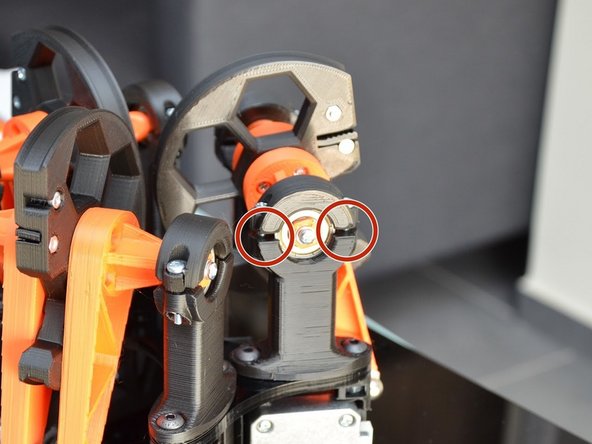
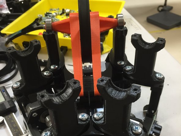
Place delta pulley assembly onto delta bearing block holder. Make sure that the FLAT side of the pulley is facing AWAY from the stepper motors.
-
Tighten bearing blocks
-
Alternate screws to ensure even tension on bearing
-
Do not overtighten - a small amount of space left between the bearing block rings is normal.
-
Repeat for 6 bearings
-
-
-
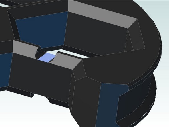
Flip your pulleys around the other way, you'll see some little slots in the acrylic plate. Use those marks to ensure that the optical interruptors line up with the slot. If so, then the mechanism is in good alignment.
-
If things don't quite match up, try swapping that pulley's bearing blocks, or turning them around. If one is slightly different than the other, swapping or turning them can be all that is needed to even things out.
-
-
-
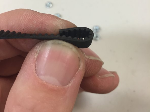
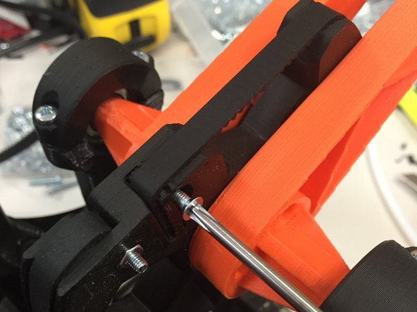
Fold belt like shown in the picture
-
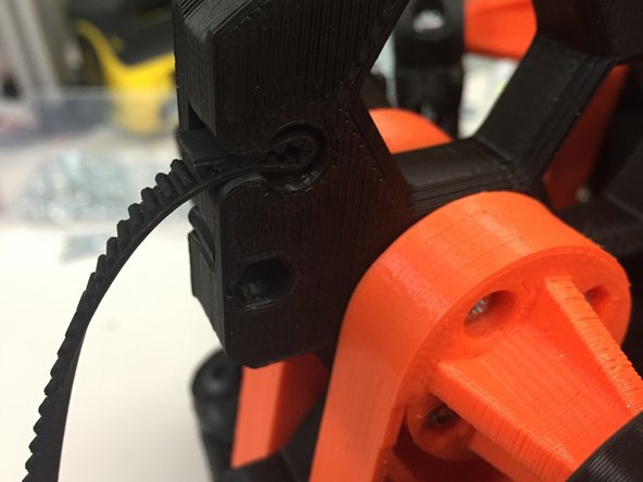
Slide the belt into the pulley, in the round hole slot, as shown.
-
Insert an M3 x 12L pan-head screw through the belt, and use a screwdriver to thread it into the pulley so that it sits flush.
-
-
-
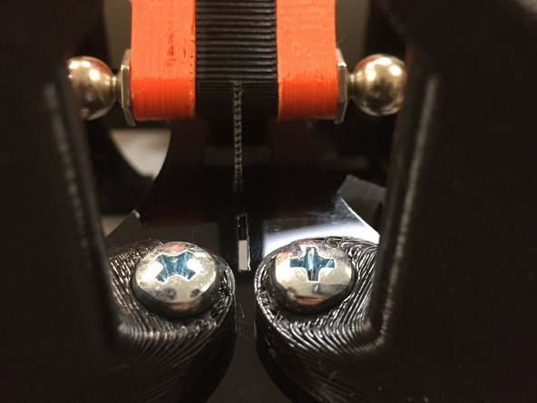
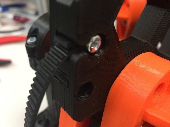
After tightening, it should look like this from the other side.
-
Ensure that the toothed side of the belt is as shown.
-
Do not over-tighten.
-
Pull to make sure belt doesn't slip.
-
-
-
Wrap the belt around the stepper motor pulley, and hold it tightly, up against the pulley, as shown.
-
NOTE: Do not cut the belt yet; we'll do that on the next step.
-
-
-
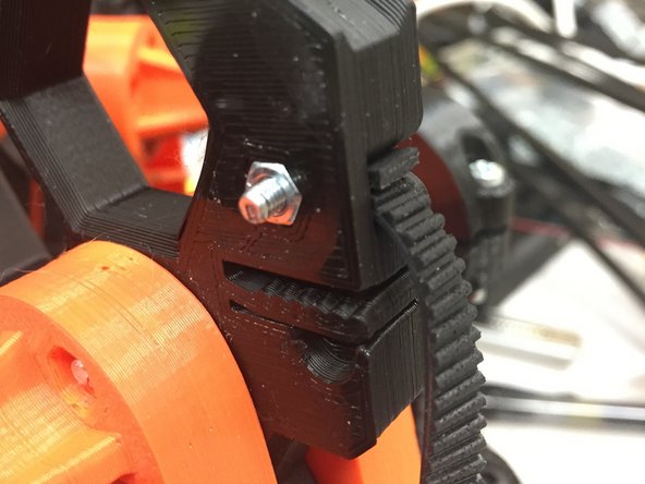
Using the belt trap as a reference, cut the belt to exact size and slip it into the belt trap as shown. Make sure there is no slack in the belt when you cut it to size.
-
Using the flat-head M3 x 12 screw, and the M3 nut, tighten the belt trap.
-
Do not over-tighten!
-
-
-
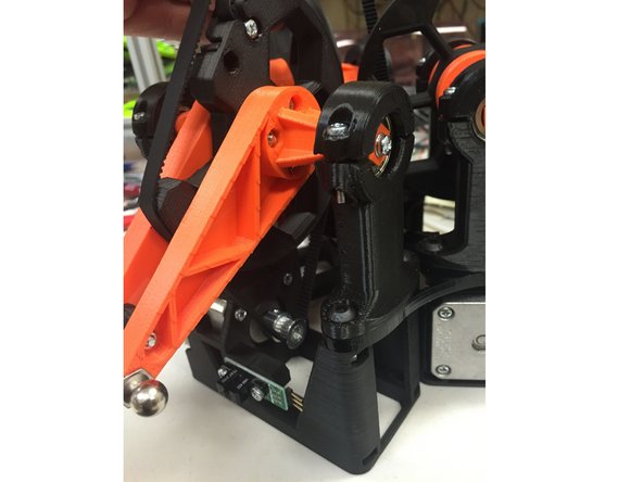
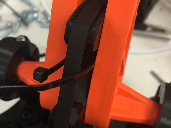
Insert the proprietary belt-tensioning mechanism through the slots in the 3D0002b pulley.
-
Thread it through the other side, as shown in the first picture.
-
-
-
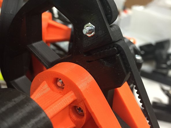
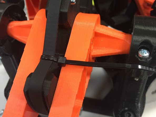
Tighten to tension the belt. Be careful not to tension too tightly (it will knock the delta mechanism out of alignment, as the PLA / acrylic bends)
-
Cut off the slack on the end of the cable tie, leaving a bit so that you can grab onto it later with a pair of needle-nose pliers, if you ever need to re-tighten.
-
NOTE: The GT2 belts will, after time, loosen up. Part of machine maintenance will be to ensure that these belts are always tightened to the right amount. The cable ties allow this to be done in sub-millimeter graduations, with zero risk of slipping.
-
-
-
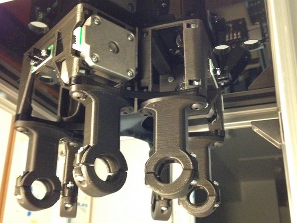
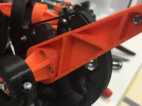
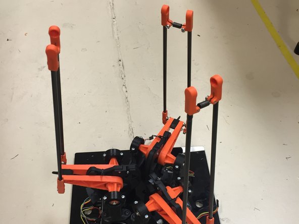
The arms are covered in this section: Assembling the Delta carbon rods
-
Attach them to the Delta Mechanism as shown:
-
-
-
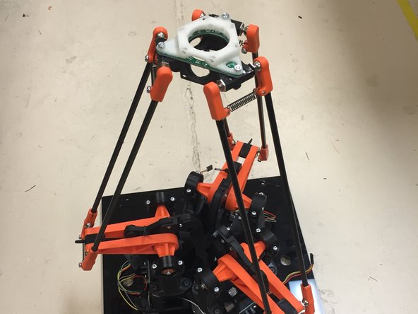
Attach end effector.
-
Note that the fan and camera module aren't shown, but they should be installed at this point. The camera should face towards the FRONT of the machine, and the fan may be mounted on either of the two remaining sides (left side is recommended).
-

Cancel: I did not complete this guide.
5 other people completed this guide.

3 Comments
One thing I noticed, is that there is quite a bit of side to side slop of the bearings in the bearing mounts. This might be useable to make sure that the interrupter is centered, and may be one of the reasons that people are complaining about seeing some variations. Initially I thought it would be good to fix this, but I think we can use it to our advantage, by checking alignment before tightening the bearings. If an optical interrupter is out of alignment, the pulley mechanism can be moved sideways, until it is in alignment, and then the bearings tightened.
Michael Anton - Resolved on Release Reply
I think step 6 was supposed to call out m5 nuts instead of m3.
NothingButGunpowder - Resolved on Release Reply
When performing step 10, be careful not to overtighten the bolts which hold the bearings in place. Tightening these bearings too much can break the 3D001a bearing block.
In step 2 it says not to attach the bearing caps to the upper arm part. The best method is to attach the caps, tighten them, and then remove them. The reason for this is the nuts can be pulled into place without placing strain on the bearing block.
Greg Smart - Resolved on Release Reply