Reputation over time
It looks like this user hasn't gained any reputation yet.
Once they have, you'll be able to view a graph of their reputation gained over time.
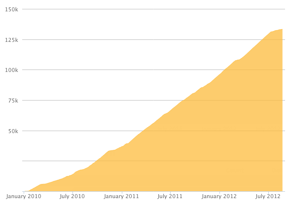
Here's a preview of what the graph will look like:
Reputation Breakdown
No reputation gained yet.
31
In the step 17 photo, the wires are soldered to the top side of the PCB, but in step 14 they are soldered to the bottom side. The bottom side would appear more logical, but does it make any difference?
Note that the 3-pin connector will protrude from the bottom of the PCB when the board is assembled. Remove some material from the 3-d printed base to allow the PCB to sit flush.
Have a look at the full assembly photo. The cable goes down and then curls back around. I assume it's to keep it away from the tools, and also to not affect the delta mechanism.
When performing step 10, be careful not to overtighten the bolts which hold the bearings in place. Tightening these bearings too much can break the 3D001a bearing block.
In step 2 it says not to attach the bearing caps to the upper arm part. The best method is to attach the caps, tighten them, and then remove them. The reason for this is the nuts can be pulled into place without placing strain on the bearing block.