
-
-
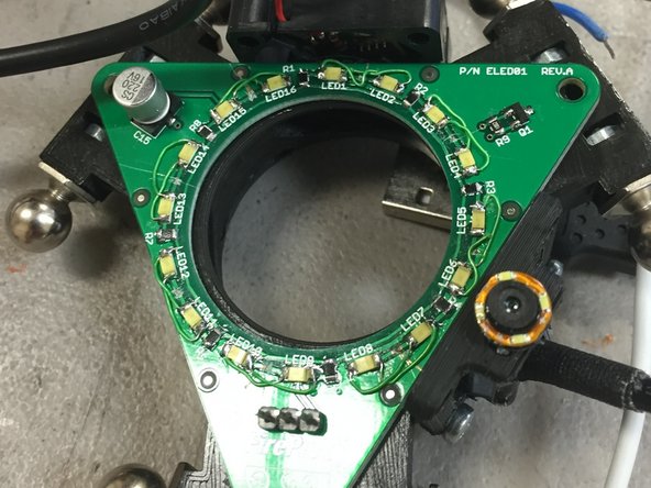
The purpose of the ELED01 PCB kit is two-fold:
-
(1) It functions as an LED ring light for the end effector. This provides illumination for the camera.
-
(2) It is intended to be an PnP Practice Kit for FirePick Delta. It is the perfect test-piece to get familiarized with OpenPnP and the rest of the system!
-
-
-
Depending on your needs, you may do any of the following:
-
(A) assemble the bare PCB into the end effector and save the assembly work for later. If this is the case, your're done! You can exit this guide.
-
(B) Assemble it manually with a solder iron, tweezers, and optionally a stereo microscope. If this is the case, continue on to step 3.
-
(C) Use your FirePick Delta and OpenPnP to place the SMT parts on this board. If this is the case, stay tuned, we'll have a guide for this up soon.
-
-
-
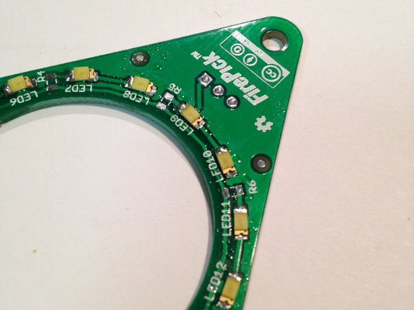
Solder LEDs, then resistors, then FET and capacitor
-
Refer to the schematic and PCB layout posted to Github.
-
Ensure that the LEDs are oriented correctly; They are polarity sensitive. The green stripe must be on the cathode side.
-
-
-
Greg Smart has proposed an experimental rework step that allows for the LEDs to be the correct brightness. The modification involves cutting the traces between LED1 & LED2, LED3 & LED4, etc, and adding rework wires to connect them in parallel instead of in series.
-
This is technically not great for the life of the LEDs, as some forum members have pointed out, however it does work in a pinch.
-


Cancel: I did not complete this guide.
4 other people completed this guide.

One Comment
My LED's had a green stripe on both sides. The cathode side had a small black square on the gold SMT mount. Maybe the green was an artifact of my scope lighting but the square is obvious.
Reef Morse - Resolved on Release Reply