
-
-
EL-CAM-ENDO (small endoscopic USB camera)
-
The bagged USB cable
-
The 3DAT0015c Camera-to-end-effector mount (downward endocam)
-
(not shown) heat shrink tubing (optional)
-
(not shown) One zip tie (optional but recommended)
-
-
-
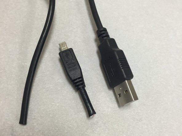
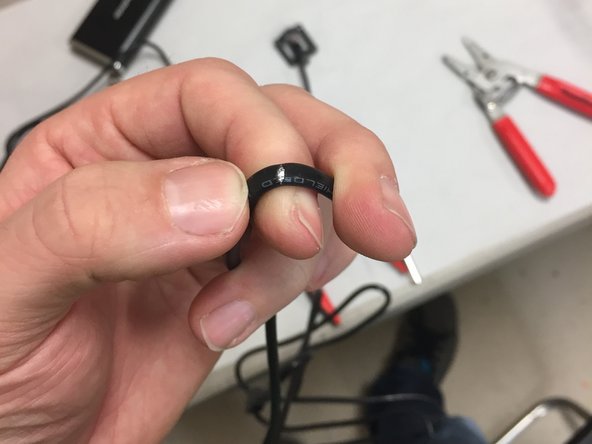
We included 2-3 USB cables in the full kits. Ensure that you've got the right one!
-
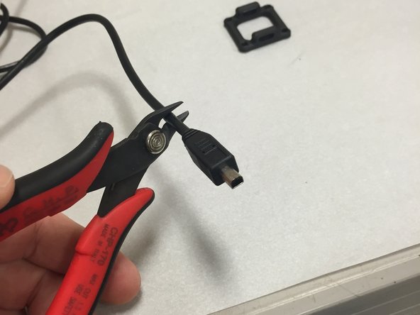
These cables have a weird non-standard end, but that doesn't matter, we're going to chop this end off in the next step.
-
-
-
Use a pair of wire cutters and chop off the weird connector end.
-
MAKE SURE YOU'RE NOT CHOPPING OFF THE TYPE-A END THAT PLUGS INTO YOUR COMPUTER. YOU'VE BEEN WARNED! CHECK TWICE, CUT ONCE!
-
-
-
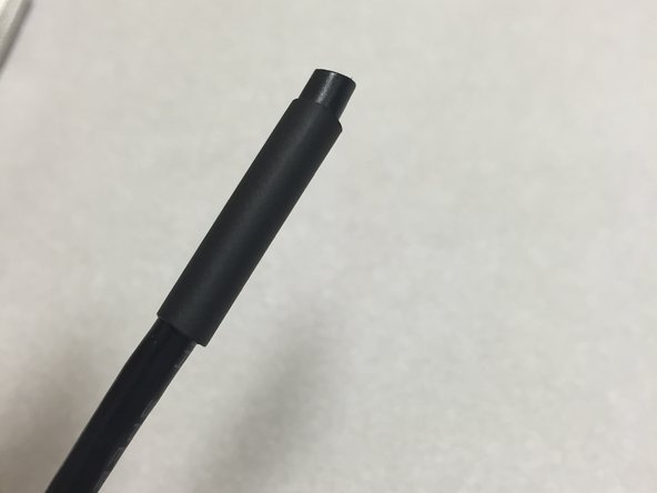
Slide on a piece of heat-shrink tubing. Do this now before you forget!
-
We use 3/16" (~5mm) heat-shrink, approximately 20mm long.
-
These were not included in the kits. You may use electrical tape on second-to-last step, instead of heat-shrink, but we recommend heat-shrink tubing. It's something every electronics guy (or girl) should have in their lab :)
-
-
-
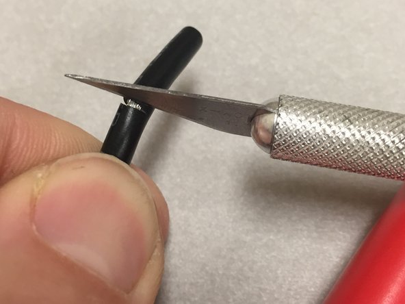
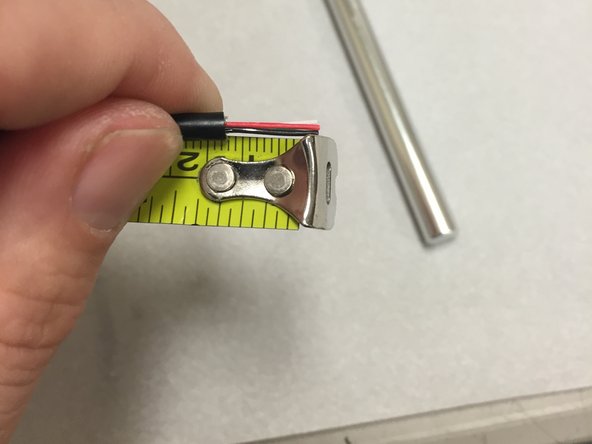
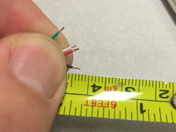
Strip off about 20mm of insulation off of the cable
-
The safest and easiest way to do this is with a X-acto style razor blade. Bend the cable slightly at the 20mm mark. Cut the outside jacket with the razor blade, VERY CAREFULLY, with just enough pressure to cut through the jacket, without cutting into the wires.
-
Some folks might have a coax cable jacket stripper in the toolbox. This might work, but we've not tested it. The X-acto method above works great for me.
-
-
-
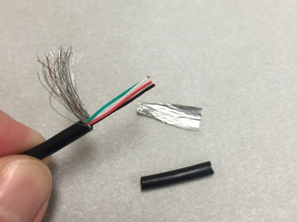
Route all of the shield strands to one side, and cut them off with a pair of side-cutters. The metal foil layer should pull right off if grabbed with your thumb and forefinger.
-
When complete, you should have four wires:
-
Red (+5V power)
-
Black (ground)
-
Green (D+)
-
White (D-)
-
-
-
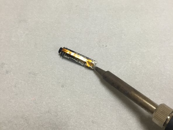
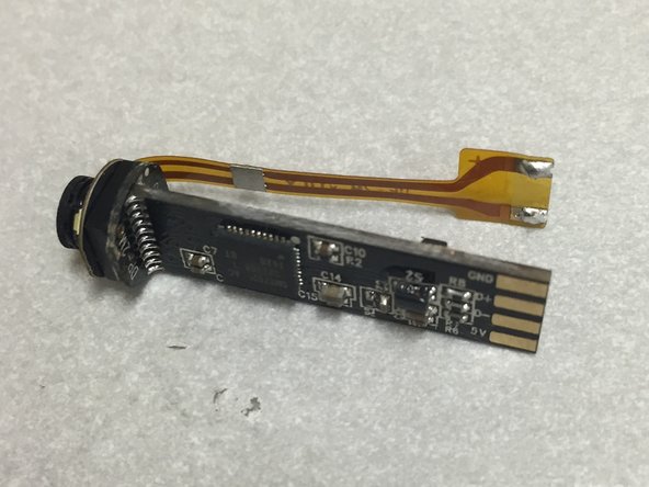
Use a soldering iron to remove the flat-flex cable.
-
Do this by heating one pad up, and twisting the cable so that the side moves away from the pad
-
Heat the other side up, twist the other direction, and the cable should separate.
-
I would not recommend using a hot-air rework station (or a heat gun) for this step. There is a risk of other SMT parts falling off. It should be quite easy to do this with a soldering iron, within a few seconds per pad.
-
-
-
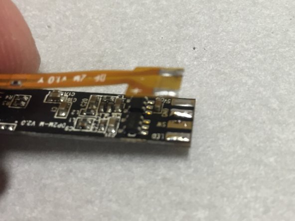
Using a pair of side-cutters, chop off the flat flex cable. We won't be using the installed ring-light. It gives too much glare on the shiny PCB's that you will be picking and placing :)
-
We do not recommend trying to peel the ring light off. It's glued down and you may risk damaging the camera.
-
-
-
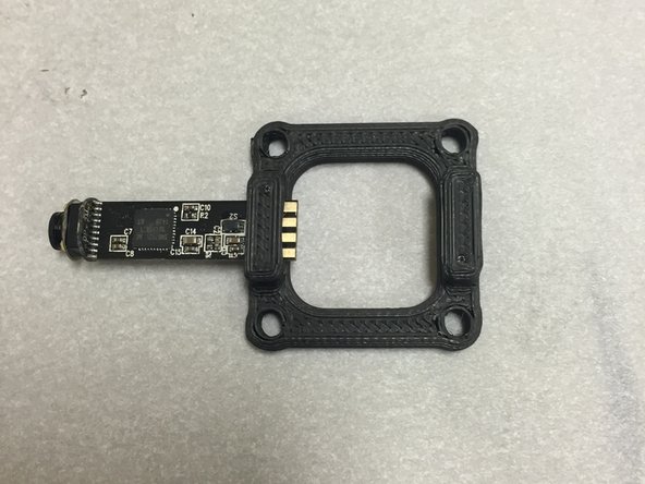
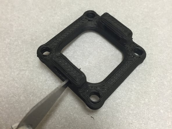
Test fit the camera module.
-
DO NOT FORCE IT IN!
-
If it seems to get stuck on the black plastic housing (we've received several reports of this), then CAREFULLY use a razor blade to remove a bit of material inside the slot, until it fits.
-
Alternatively, you may heat the PLA slightly using a heat gun, hot water, or some other means. If you use a heat gun, make sure to move it around constantly, and NEVER hold it in the same place for any length of time! You've been warned! If you heat it up too much, it will melt and the part will be ruined.
-
DO NOT apply glue or adhesives yet.
-
-
-
Strip the four wires.
-
Only strip 2 millimeters of insulation off. Most of you guys probably want to strip way too much insulation off. You know who you are.
-
We recommend this type of insulation strippers... not this kind. Or God forbid, this kind.
-
-
-
Tin the wires using a soldering iron.
-
The PVC insulation will melt and shrink during the tinning process. Your 2mm of stripped insulation from the last step will now be a few mm longer.
-
Make sure that your solder iron isn't turned up too high for this step!
-
-
-
Add some solder to the bare pads.
-
Do this only on the side of the camera that has the pads labeled: GND, D+, D-, 5V.
-
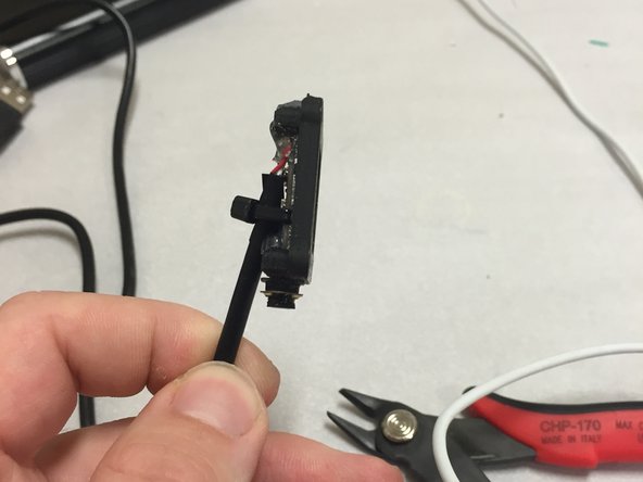
Insert the camera into the plastic piece, with the pads sticking out.
-
Note that the main camera controller IC should be facing out as well.
-
Leave the camera sticking half-way out, as shown.
-
-
-
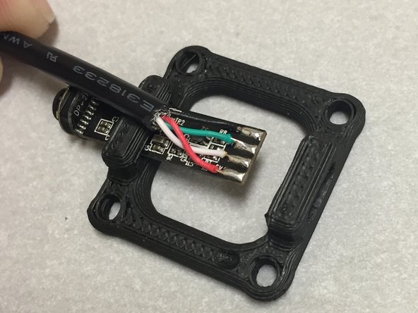
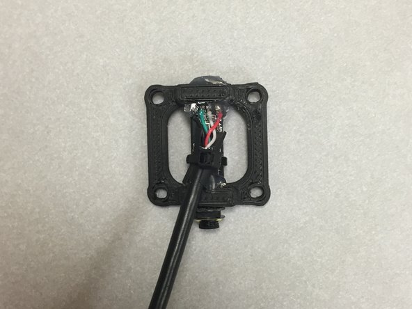
Solder the wires to the pads, as shown. Make sure that you're doing this while the camera is placed half-way into the PLA piece. The wires should go out towards the camera lens.
-
The order should be:
-
GND (Black)
-
D+ (Green)
-
D- (White)
-
5V (Red)
-
This step should be rather easy if you have just enough solder on the pads already, and the wires are tins (per previous steps). You don't need to add solder, since you'll have a soldering iron in one hand, and the wires/cable in the other. Do them one at a time, starting with black, and working down.
-
Make sure that none of the wires are shorted together, and that you didn't damage the board or the wire insulation.
-
-
-
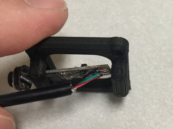
Hot glue the camera into place.
-
Once the glue sets, the camera will be be stuck like that forever. We need the camera to be as straight as possible for OpenPnP to be able to use the camera images for reference. Ensure that the camera is straight and level in all directions while the hot glue sets.
-
-
-
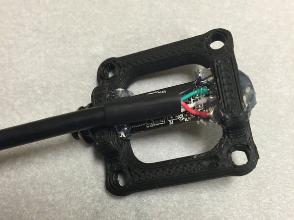
You did remember the heat shrink before you soldered, didn't you? סּ_סּ
-
-
-
Use a zip-tie to hold the USB cable to the camera module.
-
Don't squeeze it too tight! You might break your camera!
-
-
-
Set aside. This camera assembly will be used in the end effector guide.
-
Leave a comment below if you had any difficulty with this tutorial. What can we improve?
-


Cancel: I did not complete this guide.
8 other people completed this guide.

6 Comments
I'd recommend that there's a len's cap to stop grubby fingers during smearing the lens. Kaptop tape seams to work ok
This would be a great addition, I think a 3D printed version that fits the conical face of the ring light would work. Sort of like a man-hole cover. It wouldn't have to fit tightly, as gravity will hold it down.
Neil - why do the wire face down? The assembly diagram shows them coming out the top...?
Do not use the exploded diagram (assembly diagram as you put it) for anything related to wiring (period). Wiring will always be 100% covered in the Dozuki instructions, not the exploded diagram. The exploded diagram was generated from the 3D assembly in Cubify. The model in a lot of cases isn't accurate to the real machine, especially electrical stuff, because I'm not going to spend a bunch of time modeling individual wires, that's not a good usage of my time. That's why we have Dozuki. Hope that answers you question.