
Tools
Parts
No parts specified.
-
-
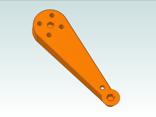
For this guide, please refer to the exploded diagram with annoted parts / Bill of Materials.
-
Note: Use the PDF linked diagram above, not the thumbnail provided by Dozuki.
-
-
-
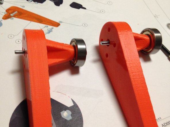
Remove the brim on the smaller end of the arm, and the support material in the two nut traps
-
NOTE: The brim and the support material may have already been removed for you by us, when we packed your kit. but it's best to double-check.
-
-
-
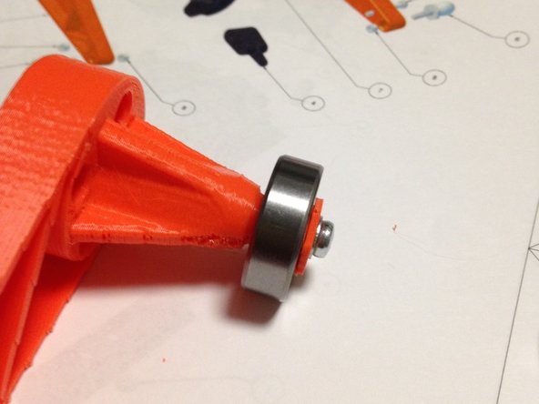
Place flat washer on M3-50mm screw
-
Place screw through 3d printed nut
-
-
-
Insert screw into arm
-
Attach M3 nut to back side and tighten until secure and snug, but not so much that the plastic deforms.
-
-
-
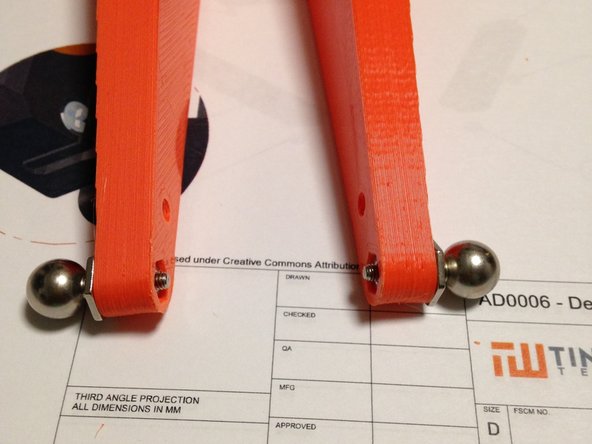
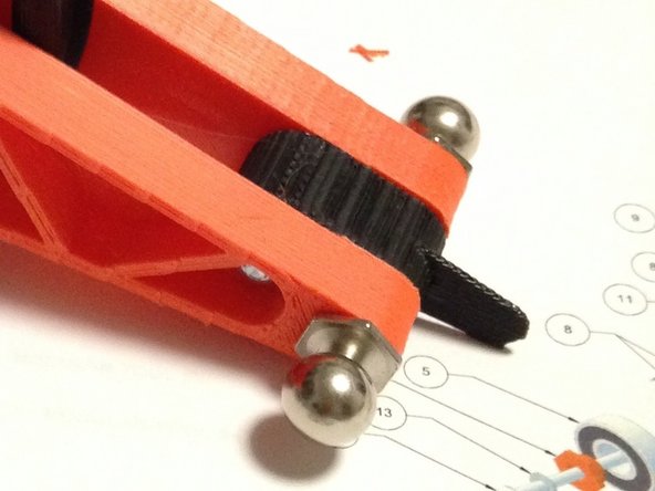
Attach ball-stud to arm
-
Secure with M3 nut. Again, tighten until secure and snug, but not so much that the plastic deforms.
-
-
-
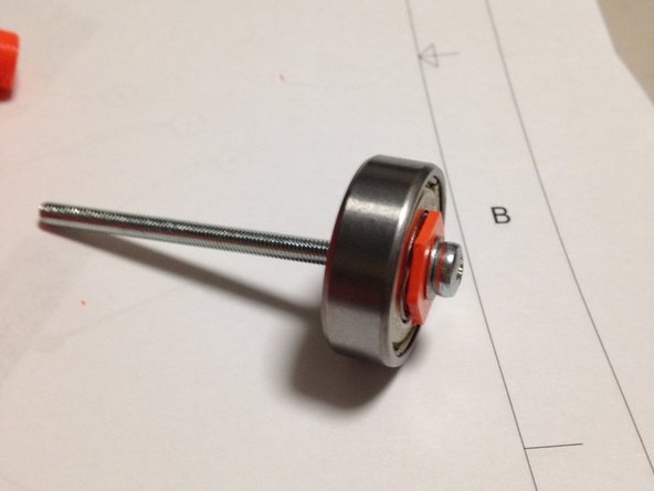
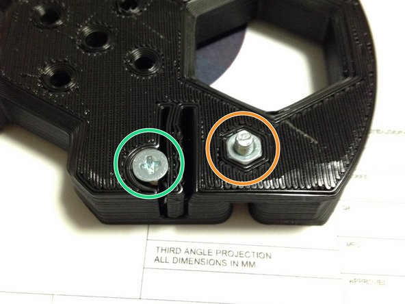
Insert M3 x 12mm L pan-head screw into pulley
-
Secure screw with M3 nut
-
Insert M3 12L flat head screw into opposite side of pulley
-
Secure flathead screw with M3 nut
-
-
-
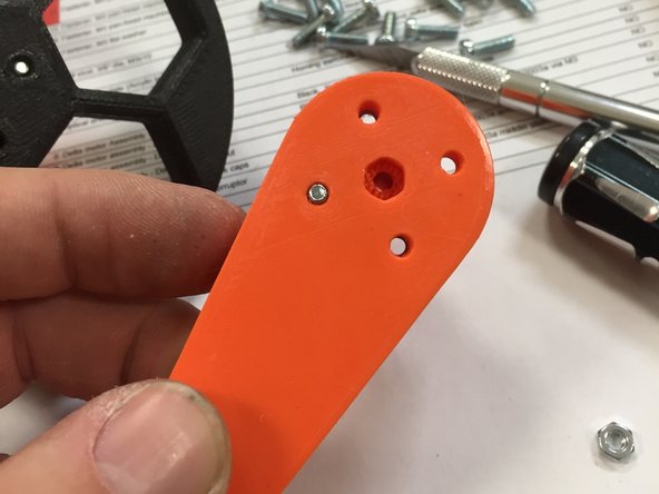
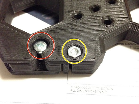
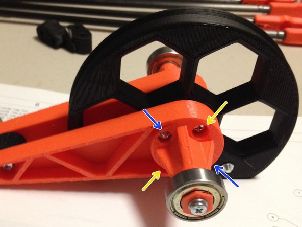
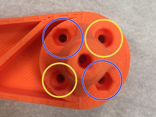
Insert two M3 nuts into each orange arm, as shown in the second picture. NOTE: Only two of the holes will accept nut traps.
-
Insert two M3 x 30mm? pan-head machine screws into each orange arm. NOTE: Only insert the screws into the ROUND counter-bored holes.
-
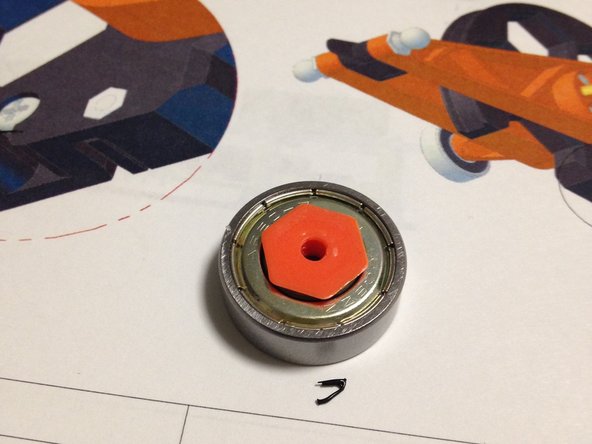
Carefully assemble both orange arms and the black pulley as shown in the first picture. The nuts and screws are caddy-corner, so when facing each other, everything should line up nicely (nut to screw, etc).
-
NOTE: Do not fully tighten until you complete the next step
-
-
-
Insert 3d printed limit switch interruptor
-
Secure with 20mm M3 screw and nut
-
Tighten all screws
-
-
-
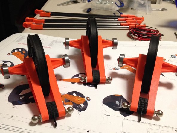
Repeat this guide until you've got three assembled pulleys, as shown.
-

Cancel: I did not complete this guide.
8 other people completed this guide.
