-
-
In this guide we will set the camera offset, based on actual measurements taken from the machine.
-
-
-
Locate the following parts:
-
A working pick-and-place machine, with nozzle and down-looking camera
-
Silly putty
-
-
-
Place the silly putty on the bed, close to X=0, Y=0, or wherever the machine home is.
-
If you don't have silly putty, you can just use the little hole on the center of the bedplate as a point of reference.
-
-
-
Jog the machine's SMT nozzle tip down into the silly putty.
-
NOTE: If you don't have silly putty, you can jog the SMT tip down to the little hole in the center of the bed plate, and use it as a refererence. Simply use the jog commands until the tip is precisely centered in the dot, and is level with the top of it.
-
Either way, write down the X,Y,Z numbers from the DRO in a safe place. We'll need to refer to them later.
-
-
-
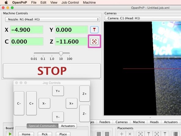
Click "Position the camera at the tool's current location'.
-
-
-
At this point, if you followed the machine.xml guide, you should be "close" to the dot, at least enough to see it on the camera. You shouldn't be more than a few millimeters off, if that.
-
Put the DRO in relative mode by clicking the X and Y readout until they turn blue and the numbers change to zero.
-
Jog the end effector around until the dot is precisely under the graticule.
-
Write the X and Y values down.
-
Take these X and Y values. Invert them, and add them to the current X and Y camera offsets in machine.xml.
-
Cancel: I did not complete this guide.
One other person completed this guide.


