
-
-
The 3D printing modular tool is split into several build tutorials. This section will cover the conical tool that fits into the end effector. The Wade extruder and final wiring will be covered in another section.
-
-
-
Insert Bowden fitting into central hole of the orange 3D printed modular tool. You may have to insert this using a press or vice.
-
Be extremely careful not to break the PLA housing or the plastic Bowden fitting, while placing it in the vice or press.
-
The black fitting must be flush with the orange triangular surface.
-
Ensure orientation is correct. See CAD model image.
-
DO NOT INSERT THE COUPLER BACKWARDS.
-
Insert second half of Bowden connector into first half. It should snap into place.
-
-
-
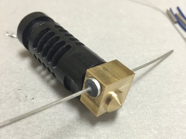
COMMENTARY: The genuine J-Head is a great hotend (one of the best that I've ever used). The ONLY complaint that I have is that the drilled hole for the included power resistor is too big.
-
The consequence being that if you're careless, and don't make a good strong connection between the power resistor and the brass block, your resistor will overheat and die.
-
The solution is to either (A) wrap the resistor in aluminum foil, or (B) use fire cement. Either are appropriate. I'll show how to do this with aluminum foil, since it's the most common of the two.
-
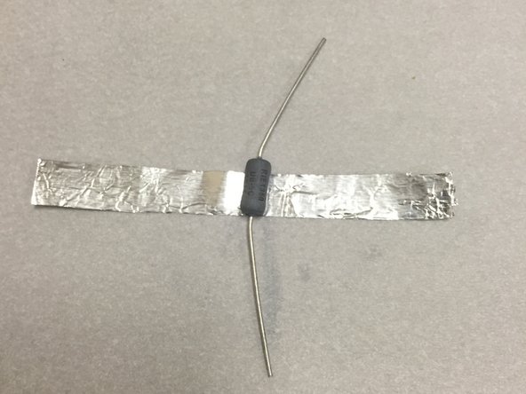
Find a piece of aluminum foil. Cut to a width slightly wider than the power resistor (it can even touch the leads at this point, we'll cut it down later with a razor blade).
-
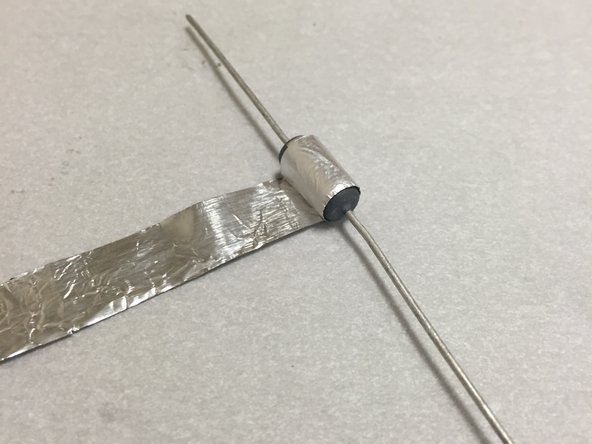
Wrap it around the resistor at least a few times and cut it. Try to carefully shove it into the brass hole, as shown. The fit should be snug, but not so tight that the aluminum foil tears.
-
You may have to try this several times before you get it right.
-
-
-
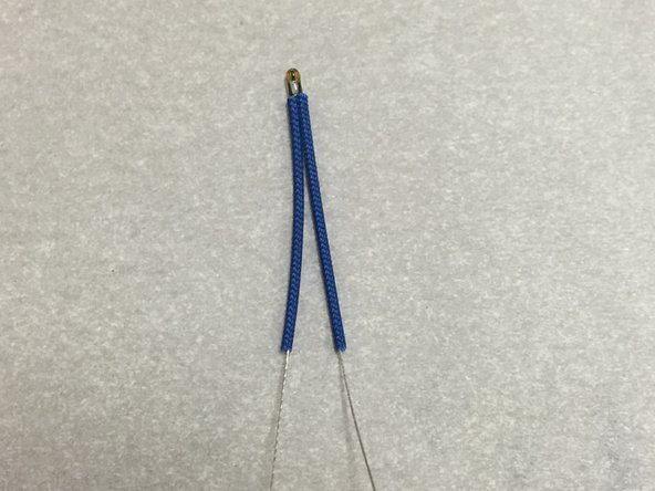
Find the thermistor (the little glass bead with the wires).
-
Make absolutely sure that you're using the one out of the 3D printing modular tool bag, and not the heated beg bag. They're different, and can't be swapped!
-
Thread the blue fiberglass sleeving onto the thermistor. Make sure that the sleeving is pushed all the way to the tip of the glass bead, as far as it will go. This sleeving is used as insulation. It works much better than heat shrink or PTFE sleeving.
-
NOTE: This is the same blue fiberglass sleeving that e3d-online sells, for their E3D v6 hotend. You can buy some from them if you ordered a barebones kit and need some.
-
-
-
Find the twisted pair wire in the 3D printer modular tool bag.
-
If you're building a barebones kit, you can scrounge this wire from a CAT5 / CAT5e cable (you get 4 pairs after removing the sleeving). Color doesn't matter. Use whatever you've got!
-
Use 3/32" (~2.4mm) or 1/8" (3mm) heatshrink, about 0.60 in (15mm) long. Place one piece over each piece of wire.
-
Strip the ends of the wire now (about 0.2 in (5mm) copper exposed)
-
-
-
Locate your ferrules. They should be in the hotend bag.
-
If you're a barebones customer, you can get these from e3d-online. They use them on their E3D v6 hotend. You can also find them in hardware stores like McMaster Carr (USA) and others, although you probably won't find them locally at a brick-and-mortar hardware store.
-
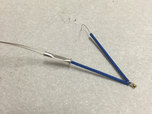
Slide the ferrules onto the twisted pair (one for each wire). Keep the barbed end towards the end of the wire.
-
-
-
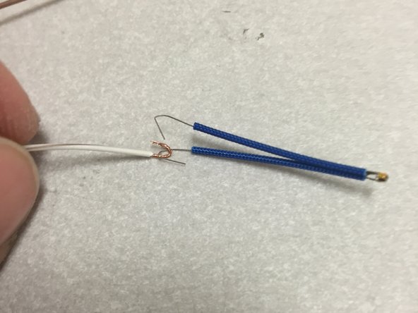
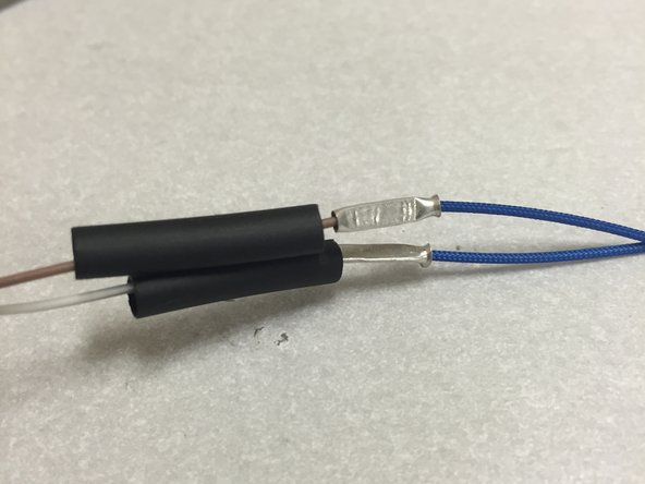
Form the thermistor leads and the twisted pair wire into hooks.
-
Hook one thermistor lead on one of the wires.
-
Use a pair of needle-nose pliars to flatten the hooks.
-
-
-
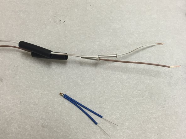
Make sure that the blue fiberglass insulation is still firmly pressed against the glass bead. Hold it there with your thumb and forefinger.
-
With your other two free hands, slide the ferrule over the wire hooks. Use your fourth free hand to crimp down tightly on the ferrule with a pair of needle-nose pliars.
-
NOTE: We have one of those fancy ferrule crimpers, but find it unnecessary for this connection. The ferrule is so thin that a pair of pliars works fine. Just make sure to squeeze really tight and check your connection by tugging at the wires (don't break them though)++
-
Now repeat the last few steps on the other wire, so that you have to perfectly crimped thermistor connections.
-
-
-
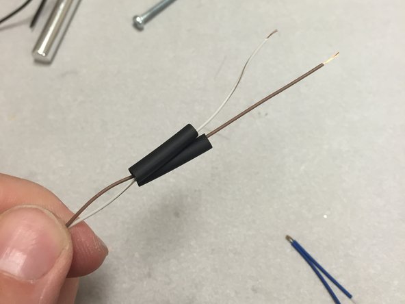
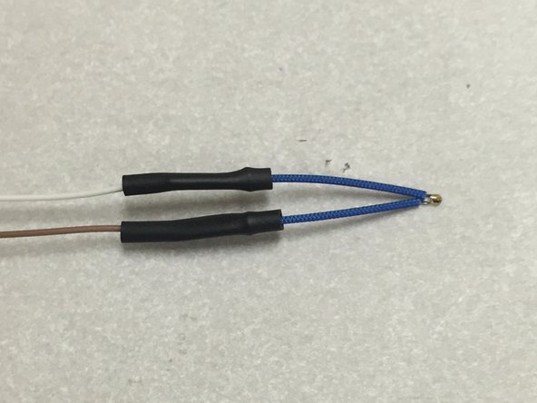
You remembered the heat shrink tubing, right?
-
Slide it over the crimped ferrules. Make sure to center it so that the ferrule does not stick out either side.
-
Use a heat gun to shrink the tubing into place.
-
-
-
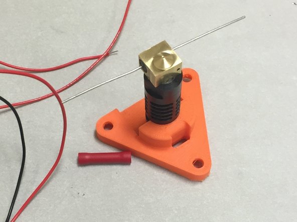
For the next few steps, use your 3DAT0017 piece as a stand while you do the crimping and wiring on the hotend.
-
Place the J-head into the 3DAT0017 printed piece. Place the 3DAT0017 onto the table work surface as shown.
-
Using 30" 24AWG wire.
-
-
-
It is HIGHLY recommended to use two crimp ferrules for the hotend power resistor connections. You can try to solder these connections, and they might work, however I've had terrible experience in the past doing this. They will break at the worst time, in the middle of your 15-hour Yoda head print.
-
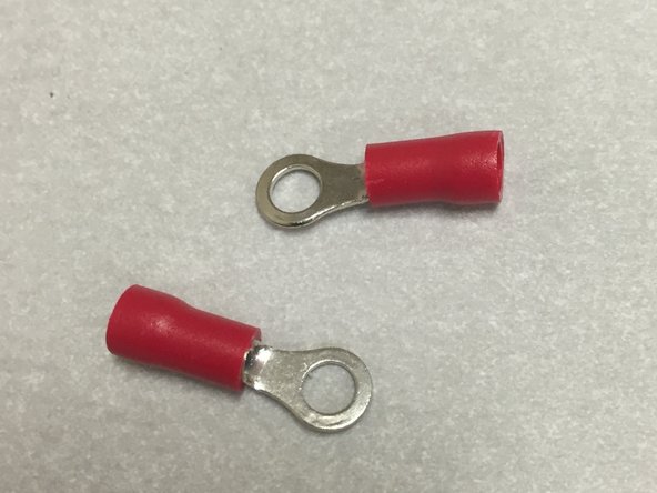
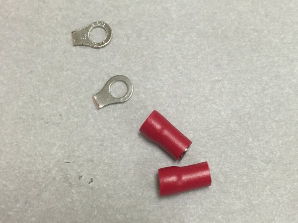
We didn't include these ferrules in the kit because the ones we bought were too small. Future kits will include them. You can use normal insulated ring terminals, as shown. We'll modify them to work:
-
We're using red (22-16 AWG) insulated ring terminals. You can find these at any hardware store, and most resourceful nerds will have a few of these in a drawer or bin somewhere.
-
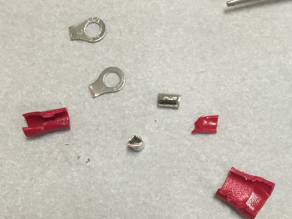
Cut the terminal ends off with a pair of side-cutters. Cut or melt the red insulation off. You'll be left with a pair of metal cylinders, as shown on the third pic.
-
-
-
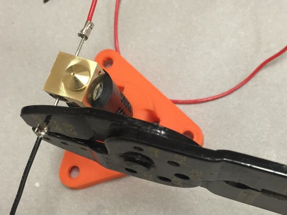
We've got all sorts of fancy crimpers in our arsonal, but we find that the crappy type works quite well. My personal favorite is the Klein Tools 1005. <3
-
Now PULL on the wires for your dear life. If the wires come loose from the crimps, start over. Keep crimping until they hold. You might want to buy some extra crimp ferrules, depending on your crimping expertise.
-
You may wish to solder the wires after crimping for good measures (just in case the crimps decide to fail down the road). This is completely acceptable, but optional.
-
-
-
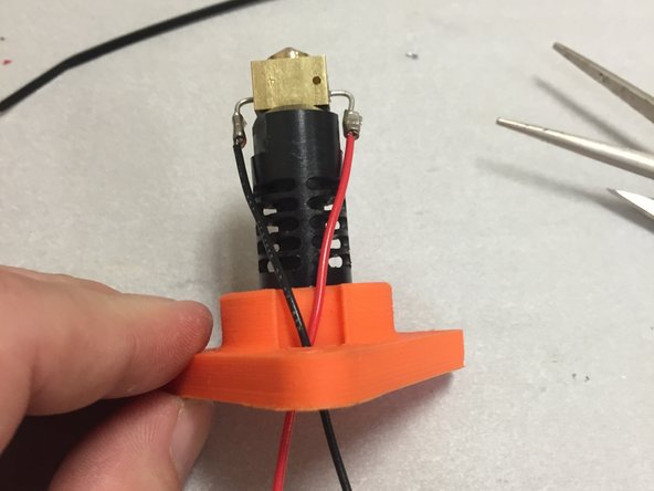
Bend the resistor leads with a pair of needle-nose pliers. Bend them as shown in the picture.
-
Route the wires through the slotted hole in the 3DAT0017 piece.
-
-
-
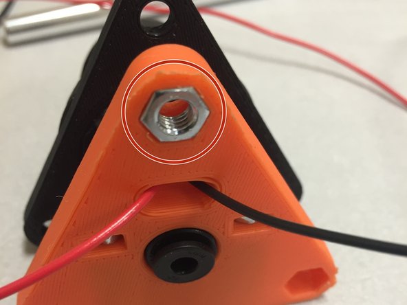
Insert the two M3 nuts into the nut traps in the top of the 3DAT0017 piece.
-
-
-
Use the included M3 x 25L to screw the 3DAT0018a clamp into the 3DAT0017 orange plastic piece. The screws should engage with the M3 nuts that were placed into the nut traps in the previous step.
-
Don't over-tighten, but make sure it's tight enough that the hotend doesn't twist or turn.
-
-
-
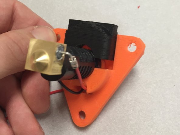
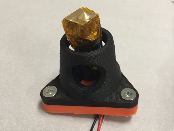
Place the 3D0024 3D printer mount body over the J-head. The big open / overhang area should line up with the 3DAT0018A clamp.
-
-
-
Press the three M5 nuts into the nut traps in the 3DAT0017. Use a pair of needle-nose pliers to get them flush.
-
NOTE: The nut traps should be a perfect fit (We worked hard to make that happen!). If they're too tight, then you may use a soldering iron to heat the nut up. It should slowly sink into place. Be careful not to get the plastic heated up too hot.
-
-
-
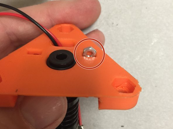
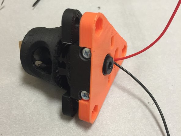
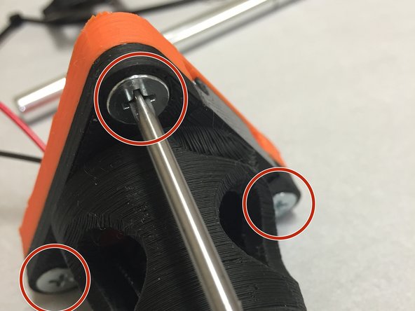
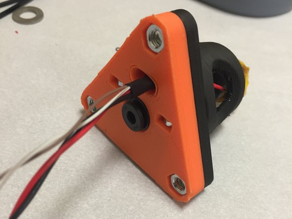
Insert three M5 flat-head machine screws (12mm long) as shown in the picture. When screwed in, they should engage with the M5 nut on the opposite side.
-
NOTE: M5 x 10L hardware was included in the first round of beta kits. These will work, however the nuts need to be fully seated, and only a thread or two will catch. The 12mm long fasteners are easier to use, but either will work.
-
-
-
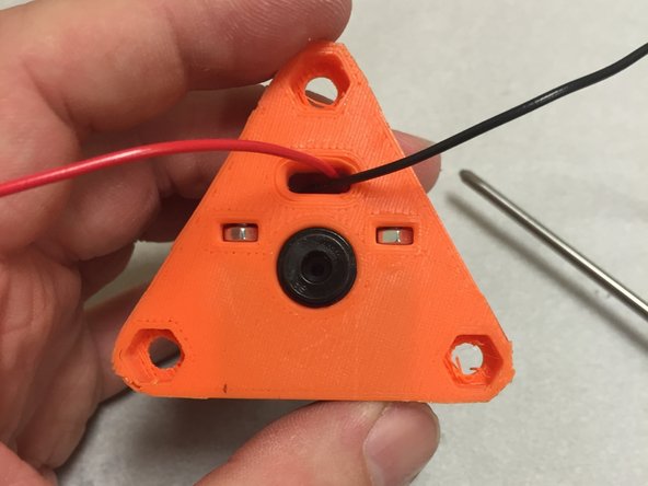
NOTE: We saved this step until now so that there was less of a chance damaging the delicate thermistor.
-
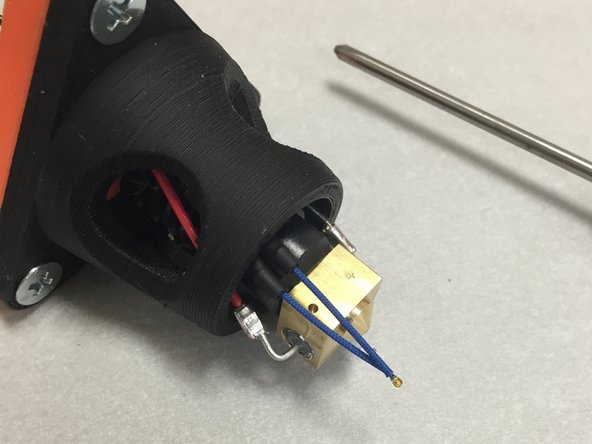
Thread the twisted pair through the cable slot in the 3DAT0017. Pull the twisted wire through until the thermistor is roughly lined up with the hotend as shown in the picture.
-
Slightly bend the thermistor leads about 3mm from the bead, slightly towards the hotend.
-
Carefully place the thermistor glass bead into the drilled hole in the J-Head brass hotend. It is critical that the fiberglass insulation is fully butting up against the glass bead, so that there is no chance that the leads or the brass housing will short out.
-
-
-
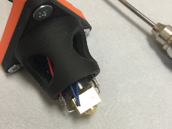
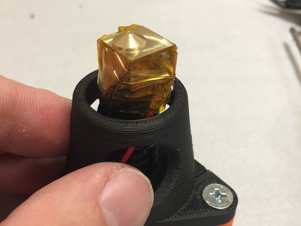
Wrap the J-Head brass heat-block with Kapton tape. Pay special attention to make sure that the thermistor is properly secured into the thermistor hole, and that it doesn't move around.
-
-
-
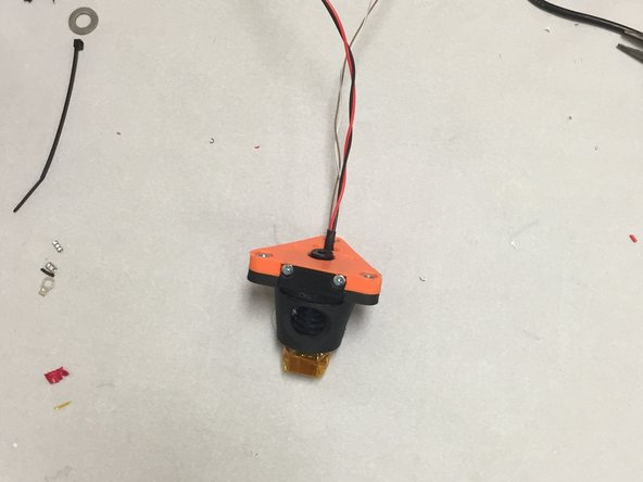
Add a small piece of heat shrink tubing on the wires, and slide it down to the slotted wire routing hole.
-
Use a heat gun to shrink the tubing onto the wires. Make sure to move the heat gun around and not keep it in one place.
-
Be fully aware that too much heat will melt the plastic, so be very careful.
-
-
-
Put the modular tool aside, and build the Wade extruder. After the Wade extruder is finish, start the final wiring on the module.
-
Leave a comment below if you had any difficulty with this tutorial. What can we improve?
-


Cancel: I did not complete this guide.
4 other people completed this guide.
