
-
-
The 3D printing modular tool is split into several parts. This section will cover the conical tool that fits into the end effector. The Wade extruder and final wiring will be covered in another section.
-
-
-
The Guidler is a Portmanteau on the words 'guide' and 'idler. The guidler serves both functions. It guides the filament into the extruder, and the idler, as its name suggests, transmits no power but applies tension to the filament.
-
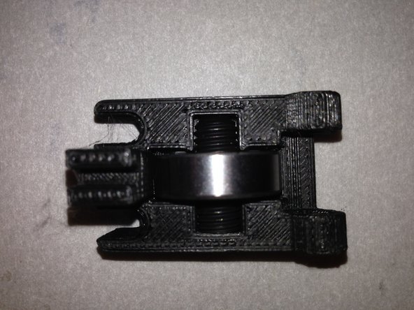
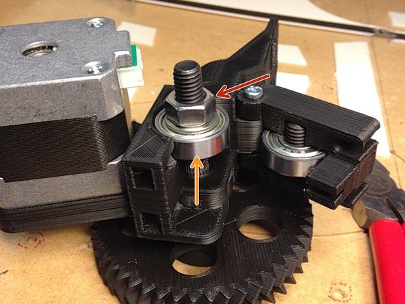
Place the FSET-M8-20L set screw into the DB608 bearing. Press this into the 3DAT004 3d printed piece.
-
You will probably need to use a pair of needle-nose pliers to secure the M8 set screw into the 3D printed piece.
-
-
-
Insert the 'FHEX-M8-60L-HOBBED' bolt through the 3DAT0002 herringbone gear.
-
Thread the 3DAT0028 spacer onto the hobbed bolt.
-
Place a DB608 bearing onto the hobbed bolt.
-
NOTE: You may find that the bearing will not easily fit over the hobbed portion of the hobbed bolt. The hobbed bolt might take some filing to get it to fit. A bench vice will work as well, as long as caution is taken to not destroy the bearing (they are not rated for large side loads).
-
-
-
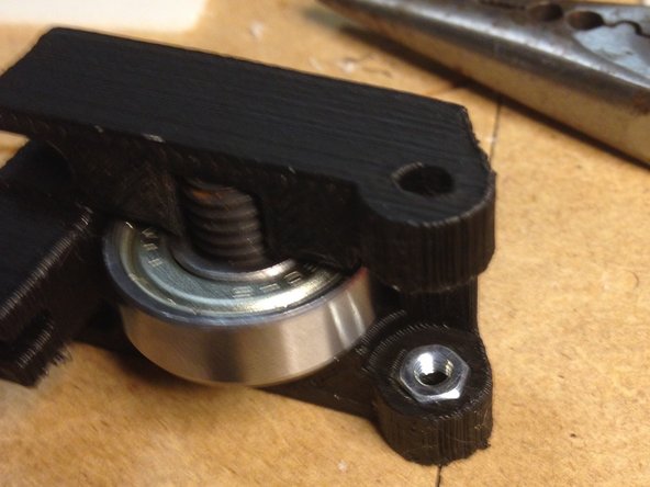
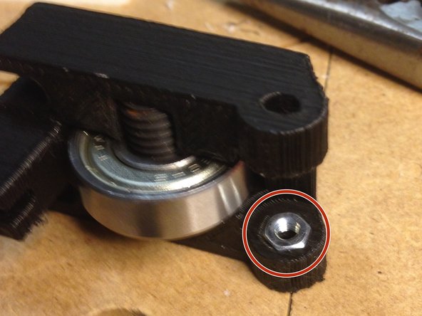
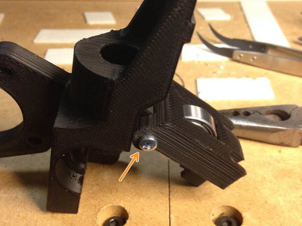
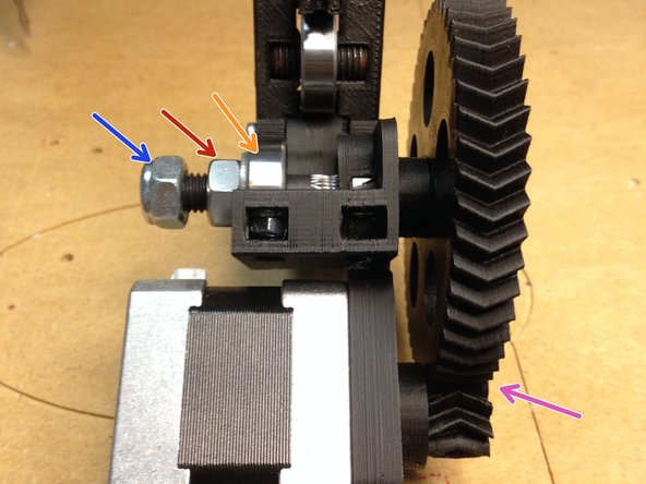
Insert nut into mount
-
Attach bearing mechanism to motor mount using M3 screw
-
-
-
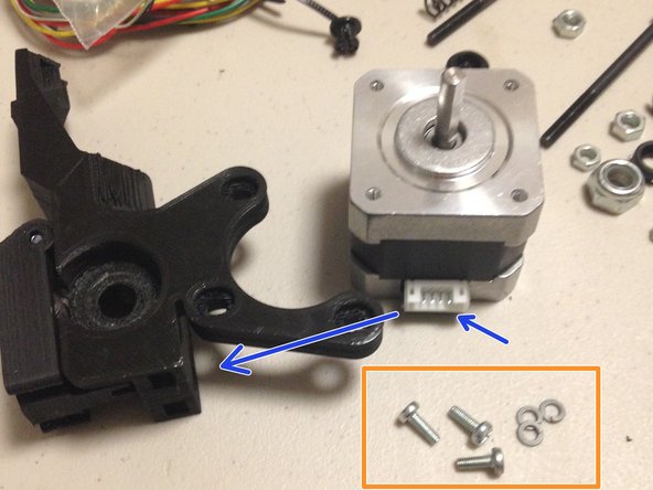
Align stepper with connector towards mounting bracket
-
Attach with 3 M3 screws and locking washers
-
-
-
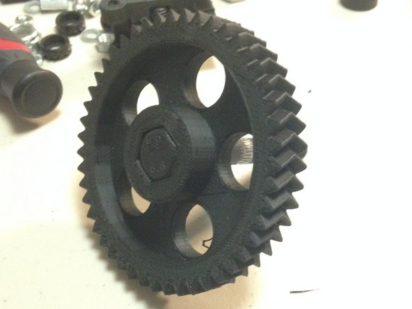
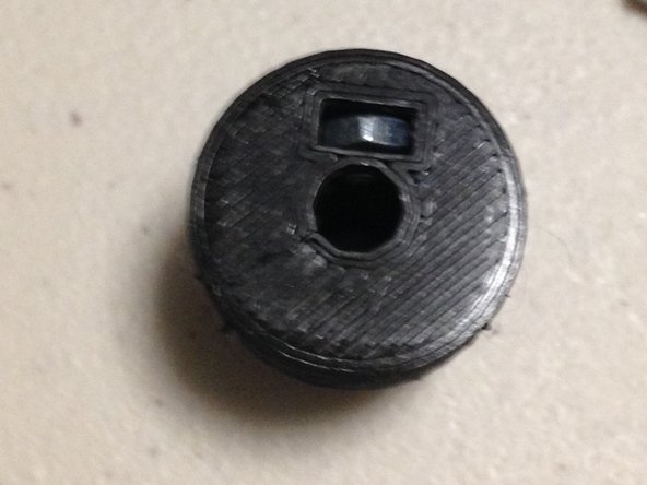
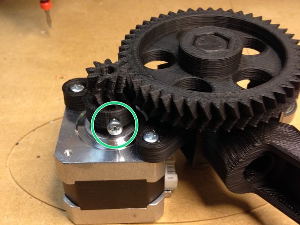
Insert M3 nut into gear
-
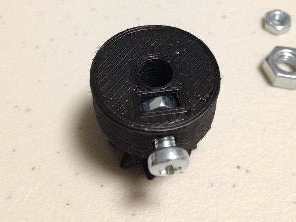
Insert M3 screw and partially screw in, but not far
-
Attach great to stepper; ensure screw is aligned to flat edge of stepper shaft
-
Leave screw loose until large gear is added (next step)
-
-
-
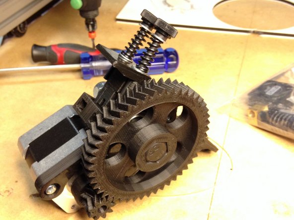
Insert large gear into mounting bracket hole. You may need to wiggle the gears back and forth to get good alignment.
-
Insert bearing onto bolt
-
Fix bearing into place using M8 nut
-
Add lock nut to end
-
Tighten set screw on small gear
-
-
-
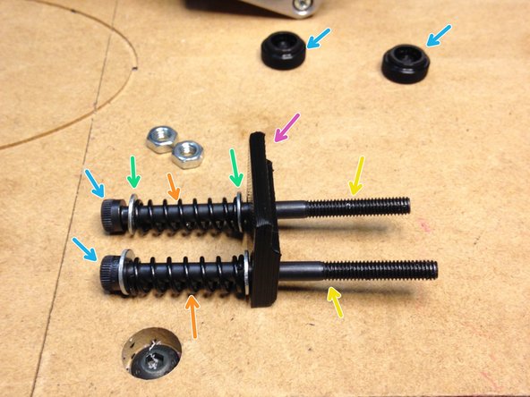
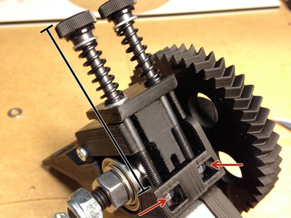
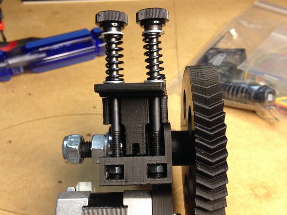
Add end caps to screws
-
Add flat washer to each screw
-
Add spring
-
Add another flat washer
-
Add tension plate
-
Insert nuts into mounting bracket
-
Screw tension mechanism into nuts
-
-
-
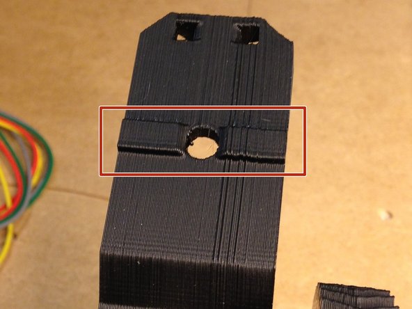
Trim the mounting bracket by removing a small portion of the ridge on the arm. See pictures.
-


Cancel: I did not complete this guide.
4 other people completed this guide.
