
-
-
Use the full-size PDF exploded diagram for reference, when following this guide.
-
NOTE: Use the PDF link above, not the Dozuki thumbnail to the right.
-
-
-
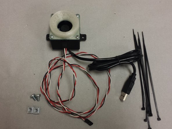
Hardware: 4x M3 x 10mm pan-head machine screws, 4x M3 nuts, 4x M2 x 8mm pan-head machine screws, 4x M2 nuts, 2x M5 x 10mm pan-head machine screws
-
USB camera module
-
LED ring light PCB
-
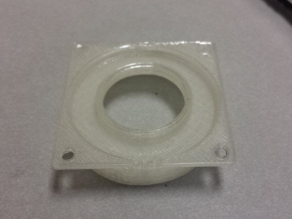
3D printed camera housing
-
3D printed LED ring light diffuser
-
NOTE: The two M5 extrusion nuts should be in the frame. They were installed during the frame build guide.
-
NOTE: Your LED right light PCB does not need to be assembled at this point. This board was sent un-assembled so that you can use it as an SMT PnP practice kit! You may assemble it manually if you'd like, or leave it out until your machine has been commissioned.
-
NOTE: The OpenPnP software that uses the up-looking camera is still in heavy development. That being said, we believe that it will be ready for prime-time in the coming weeks.
-
-
-
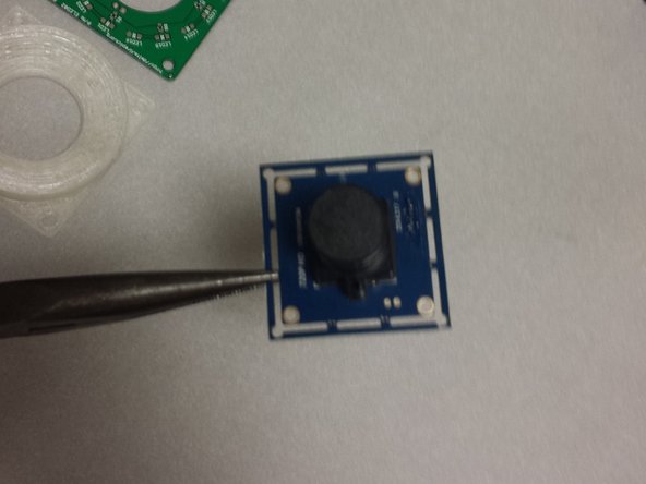
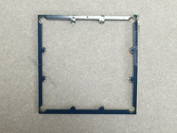
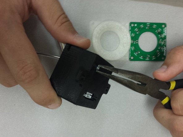
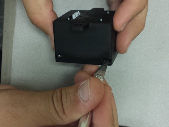
The ELP USB camera comes from the factory with a frame. Carefully snap this off using a pair of needle-nosed pliers.
-
-
-
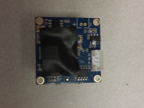
You may have noticed a piece of black tape on the back of the ELP camera module. Do not remove it. Your image quality will suffer if you remove it (this has to do with light hitting the sensor through the PCB vias... this module is a bare CCD die on the PCB).
-
If your camera didn't come with tape, or you removed it, find some black tape, and cover the back, especially in the center. Electrical tape will do, but we're partial to gaffer tape.
-
-
-
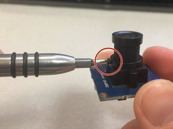
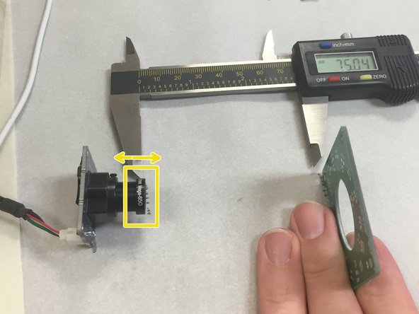
Before placing the camera into the housing, we will adjust the focus.
-
Loosen the little set screw on the side of the camera M12 screw housing.
-
Using a piece of paper and a small PCB or business card to make a focus-setting jig. Set the business card about 75mm away from the tip of the camera lens.
-
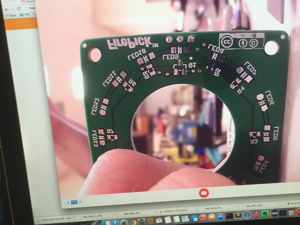
Adjust the focus by turning the camera lens housing into (or away from) the housing. Try to get this as sharp as possible.
-
Tighten the set screw on the M12 housing to keep the lens from loosening.
-
-
-
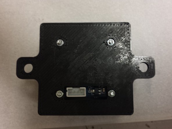
Insert 4x M2 nuts into the back side of the housing.
-
-
-
Use four M2 x 8mm pan-head machine screws to fasten the camera to the housing.
-
-
-
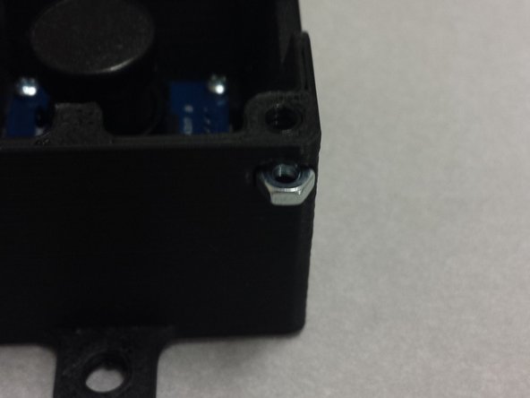
Insert 4x M3 nuts into the side of the housing
-
You might have to remove a bit of PLA overhang support from the screw holes.
-
-
-
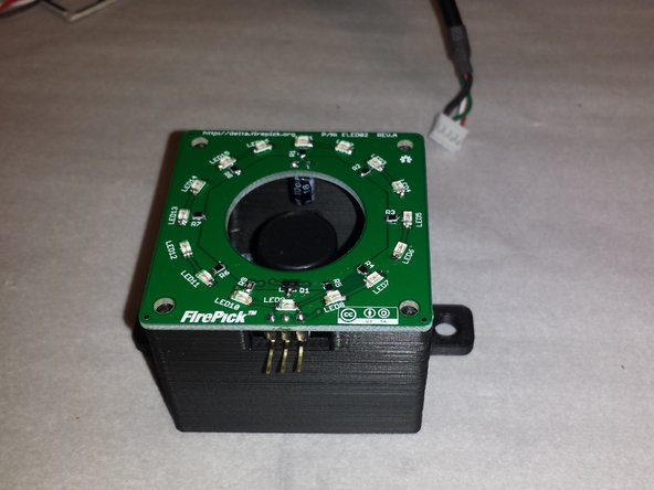
Place the right light onto the housing as shown.
-
-
-
Locate Ring Light Diffuser.
-
Remove overhang support, if present.
-
-
-
The diffuser will have three clearance holes for the ring light connector pins. Make sure that these holes line up correctly.
-
-
-
The cable between the ring light can be either crimped or soldered directly to the board. The former is recommended.
-
We will crimp this cable in the following steps.
-
-
-
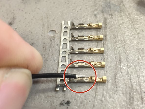
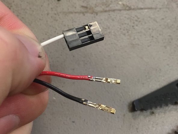
Strip the included 42" wire included in the Uploading Camera Hardware Set by 2-3 millimeters. Refer to the picture. Do not strip more than this, as the crimp will not be usable.
-
-
-
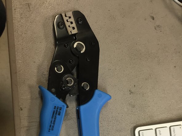
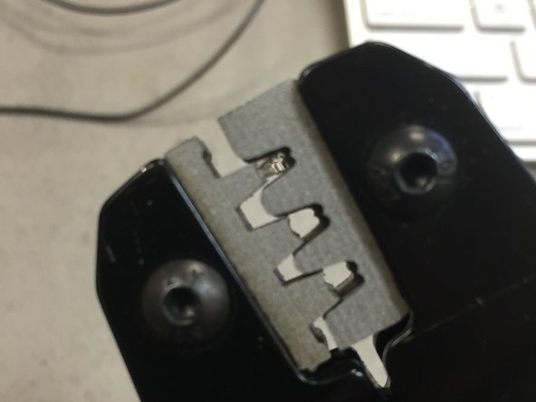
Place the crimp pin into the crimper.
-
Note that the crimper has two different crimping zones: The insulation zone and the wire crimp zone. Make absolutely sure that the crimp pin is inserted properly into the crimper, otherwise the crimp will be unusable.
-
-
-
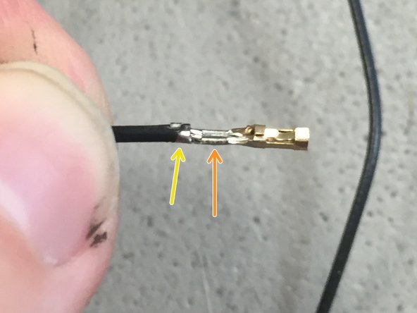
After crimping, inspect the crimp.
-
The wire should be crimped in the wire crimp zone.
-
The insulation should be crimped in the insulation crimping zone.
-
-
-
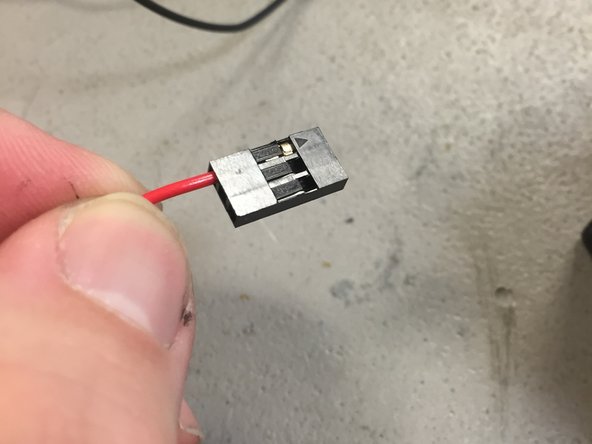
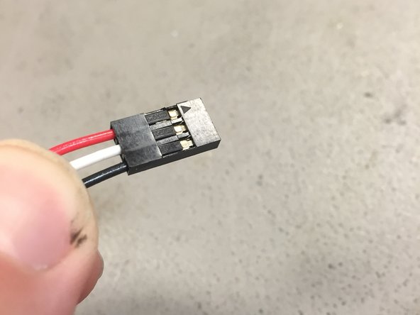
Insert the wires as shown:
-
Pin 1: Red (+5V)
-
Pin 2: White (SIG)
-
Pin 3: Black (GND)
-
Note: The pinouts on the two ends do not match. This end connects to the CAMERA board.
-
-
-
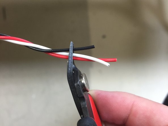
Tightly twist the wires for the entire length.
-
Cut the wires to an even length on the end.
-
-
-
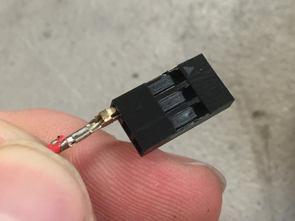
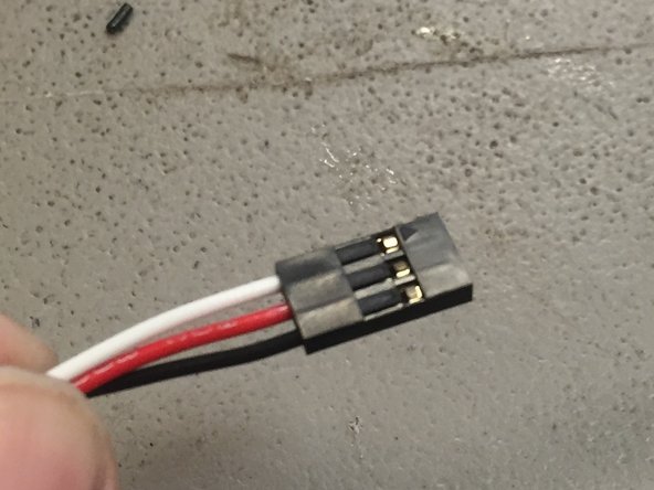
Insert the crimp pins into the second housing.
-
The pin order should be as follows:
-
Pin 1: White (SIG)
-
Pin 2: Red (+5V)
-
Pin 3: Black (GND)
-
Note: The pinouts on the two ends do not match. This end connects to the EMC02 board.
-
-
-
Secure the diffuser to the housing with 4x M3 x 10mm pan-head screws.
-
-
-
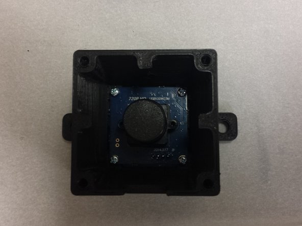
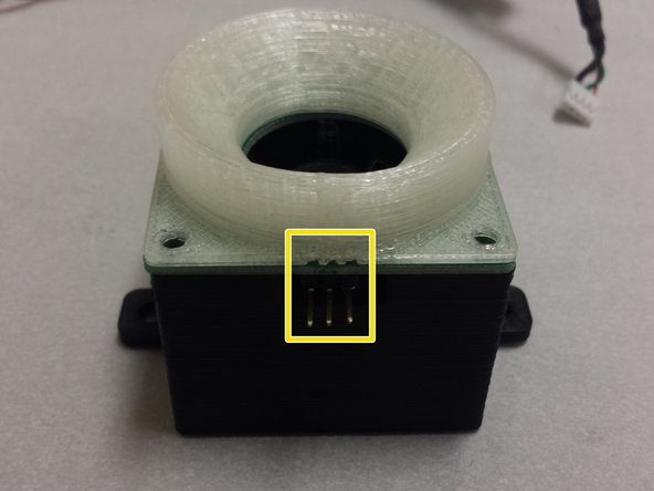
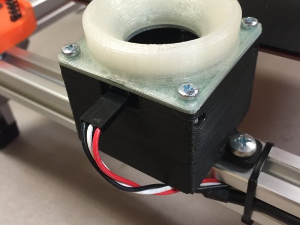
At this point, your camera should look like this.
-
(NOTE: The two extrusion nuts should be inside the frame, not loose! They were installed during the frame build guide)
-
In the next few steps, we'll install this module onto the machine, and connect it to the motion controller.
-
-
-
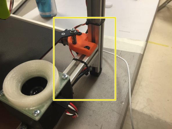
Mount the camera module on the frame using the included M5 x 10mm pan-head machine screws (NOTE: M5 x 10mm button-head cap screws will also work here, if you're building a barebones kit)
-
Two extrusion nuts were placed into the front horizontal extrusion during the frame build. These two exrusion nuts are where the camera mounts to. The camera should end up on the FRONT of the machine.
-
Center the camera (150mm (4 15/16") from the outside edge of the machine).
-
Connect the LED cable as shown (RED wire on the RIGHT side).
-
-
-
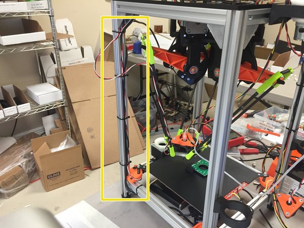
Route the LED cable up the frame to the EMC02.
-
-
-
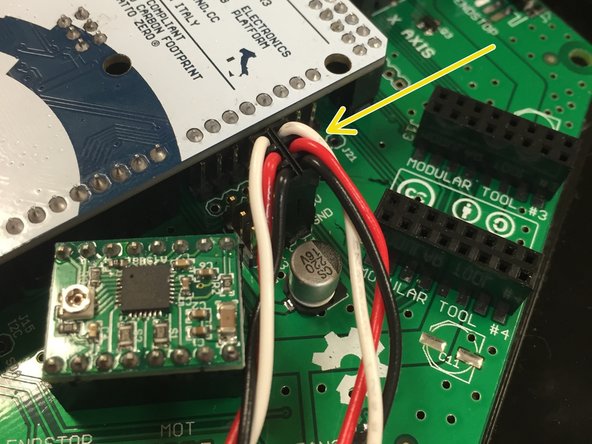
Connect the LED cable to the EMC02, to J1. Ensure that the white wire is pointing towards the Arduino.
-


Cancel: I did not complete this guide.
5 other people completed this guide.

11 Comments
Would it be possible to include a lens dust cover that goes over the diffuser as reaching inn and trying to remove the one off the camera lens is a bit fiddly.
Douglas Pearless
Douglas Pearless - Resolved on Release Reply
Douglas, that's one of the things on my list, but it's lower priority and I won't have time to do it before we get basic PnP working. I do take pull requests, though.
Recommend adding some pictures and instructions about how the camera LED ring connects to the EMC02.
I think the bottom silk on the up-looking light board is backwards for the CAP polarity. I think the cap on your board in the picture for this guide is mounted backwards? (I think the square pad is ground if I am not mistaken....)
Peter Betz - Resolved on Release Reply