
Tools
Parts
-
-
Gather the following:
-
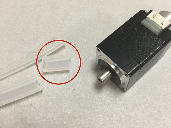
SMT nozzle / motor bag
-
SMT modular tool hardware bag
-
DTS-0.0625ID-0.1875OD-500L (the small silicone tubing)
-
3DAT0006a NEMA 8 tool mount
-
Not shown: DTS-0.1875ID-0.3125OD-150L (the large silicone tube)
-
-
-
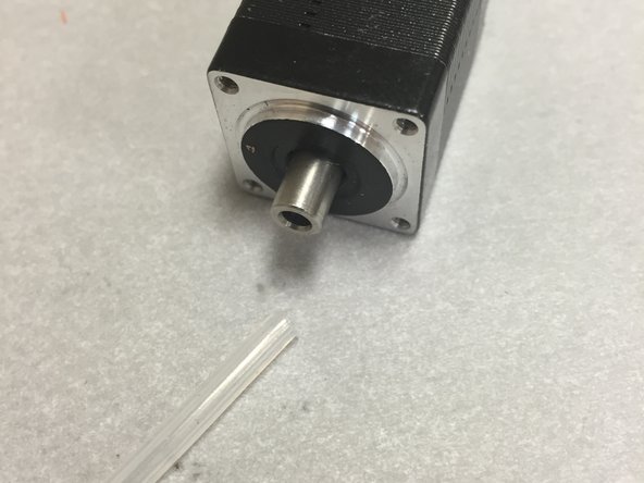
Start by cutting off about 12-13mm of the large silicone tube (DTS-0.1875ID-0.3125OD-150L). Try to get a nice clean perpendicular cut.
-
-
-
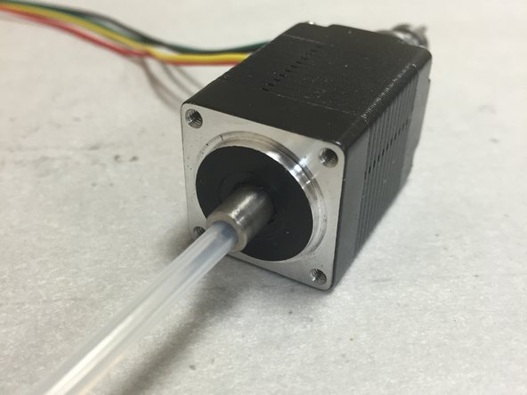
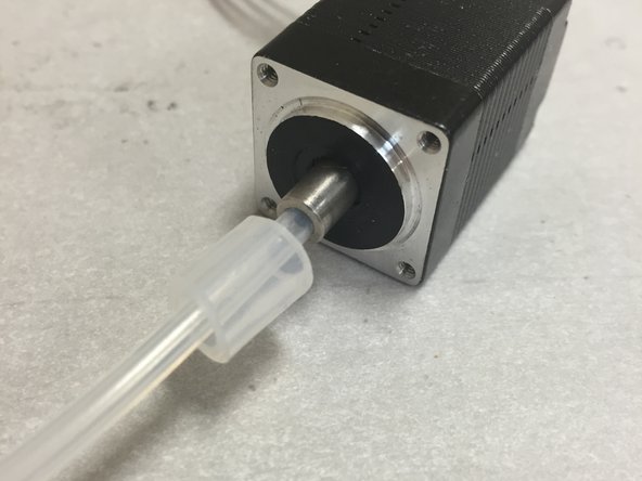
Insert the small tubing into the hollow shaft. Shove it down as far as it will go (~3-4 mm or so).
-
-
-
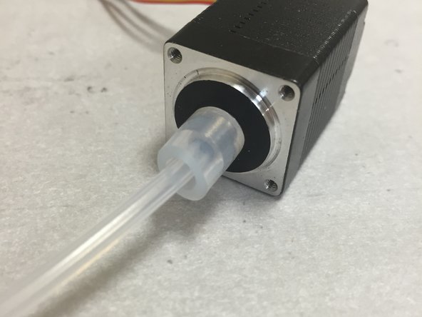
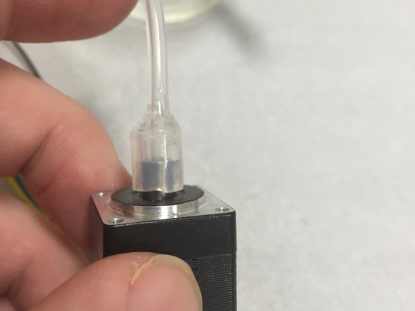
Slide on the large tubing cut from the previous step.
-
Slide it down onto the hollow shaft
-
Ensure that there is at least 1mm between the bottom of the silicone tubing and the motor. This will need to rotate freely.
-
-
-
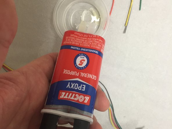
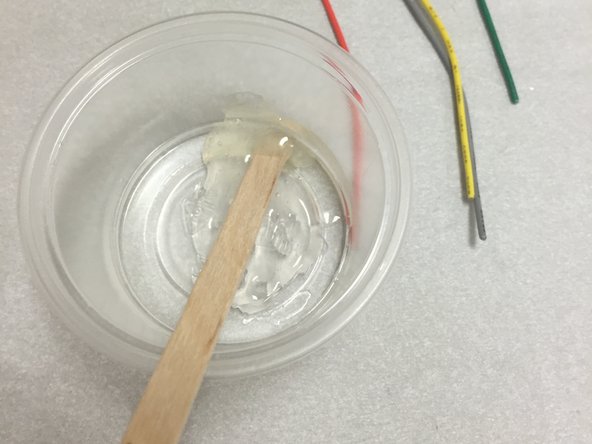
Mix up a bit of 2-part epoxy (not included in the kit). General purpose clear epoxy should work fine, this can be purchased from any hardware store, and even most big-box stores in the hardware section.
-
-
-
Add the epoxy to the gap between the large and small silicone tubes.
-
Work quickly! The epoxy should begin to harden within a few minutes, tops.
-
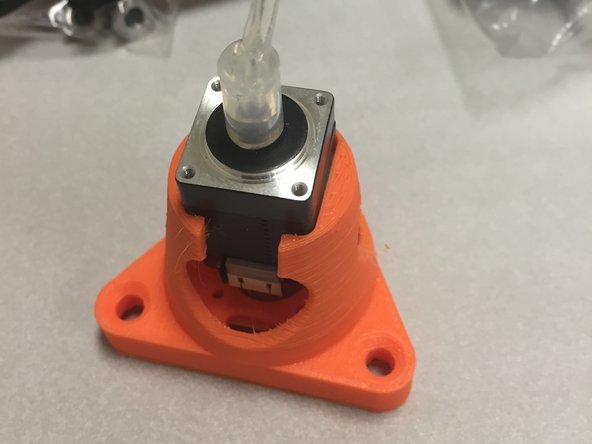
The orange 3D printed piece may be used as a stand to hold the motor in a level position. Do not fasten at this time.
-
Do not let the epoxy drop down onto the motor.
-
-
-
Wait for the epoxy to dry.
-
While you're waiting, here's a picture of a cat with a chicken hat on his head.
-
-
-
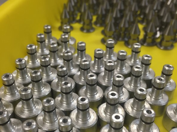
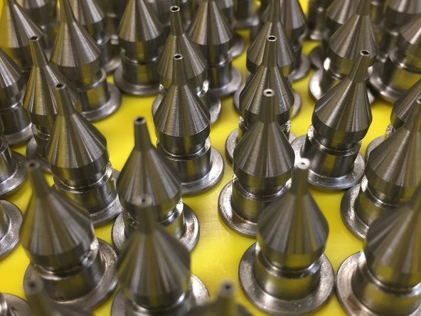
We already did this step for you, if you purchased the kit from us. You may spend a second and take in the beauty of fine machining work that we had commisioned by brave souls with superb numerical control skills.
-
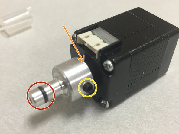
There are two o-rings in this assembly:
-
One on the outside, that holds the nozzle tip onto the extender.
-
One that goes between the aluminum extender and the stepper motor shaft. The primary duty of this o-ring is to provide a strong seal so that the vacuum is not lost in the gap between the two pieces.
-
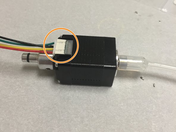
There should be a set screw holding the aluminum extender onto the shaft. Ensure that it's tight, but not so tight to strip the hex key hole.
-
Ensure that the two nozzle tips fit well when placed onto the aluminum extender.
-
-
-
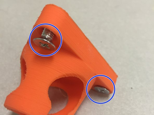
Insert the M5 flat-head screws into the three holes, as shown.
-
Place M5 nuts in the nut traps, and tighten.
-
-
-
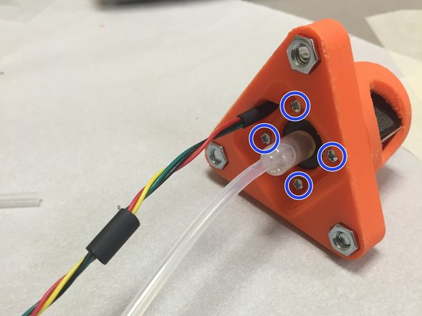
Insert the stepper motor into the 3D printed housing, making sure to insert the side with the M2 screw holes.
-
Use the included M2 pan-head screws to secure the stepper motor into place. Do not over-tighten.
-
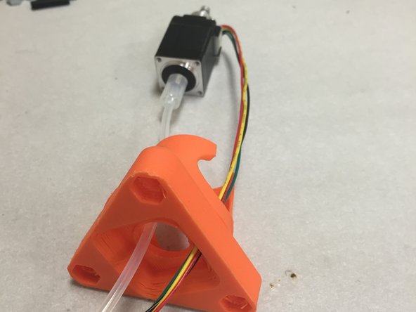
Use a cable tie to keep the stepper motor cable secured. Thread it around the motor, and make sure to slide the zip tie towards the flange, so that the head doesn't stick out of the conical section.
-
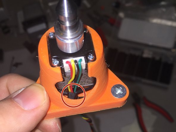
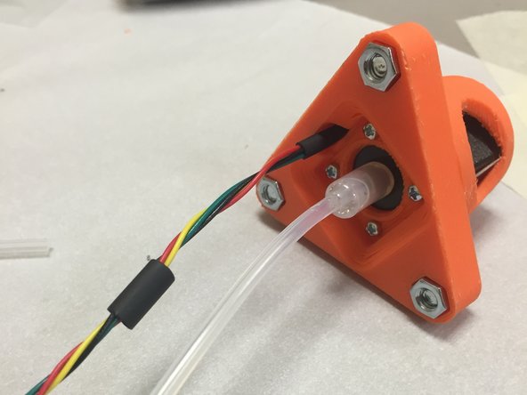
Ensure that the stepper motor cables are exiting the designated slot, as shown in the picture.
-
-
-
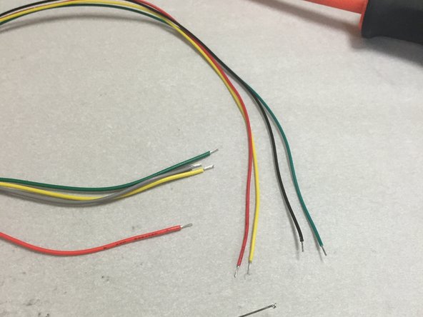
Find the included four pieces of 18" (~450mm) wire in the hardware bag. Make sure not to use the two 14" (~350mm) pieces of wire (red and black). Those will be used for the vacuum pump.
-
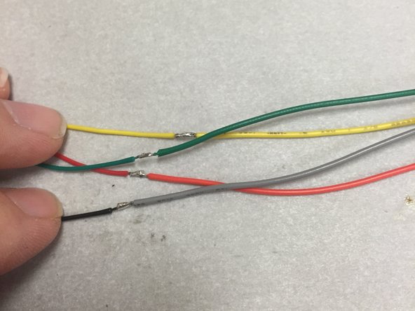
Strip and tin one end of the extra included wires. Also strip and tin the end of the NEMA 8 stepper motor cable wires, if not done already.
-
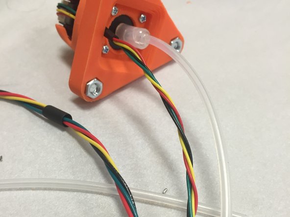
Solder the wires together, using the same color (the exception being gray -- use the black wire for this).
-
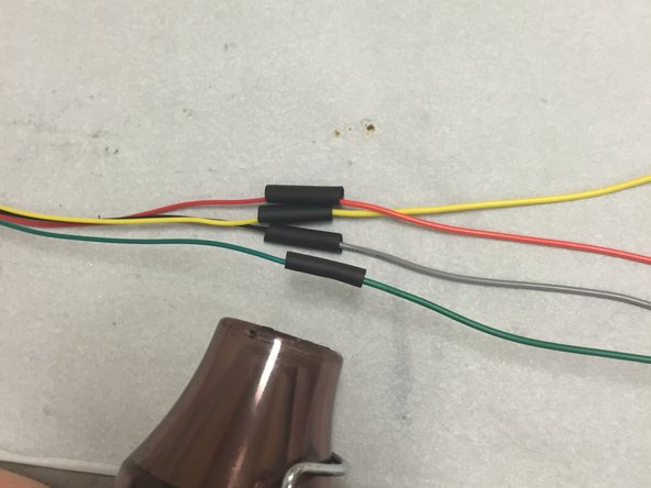
Cover the soldered connections with heat shrink tubing. Use four pieces of 3/32" heat shrink tubing (2.38mm), about 12-14mm long. Note, these pieces weren't included in the kits.
-
Shrink the tubing using a heat gun.
-
-
-
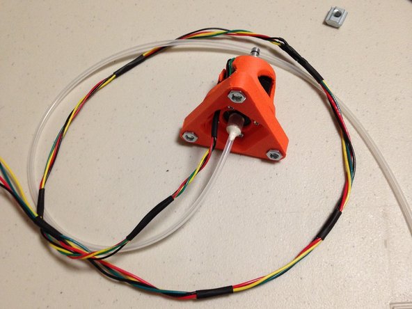
Twist the wires tightly, for the entire cable length.
-
Use small (~6-8mm long) pieces of 3/16" (~4.76mm) heat shrink tubing, and shrink these into place, approximately every 40-50mm (2in) along the length of the cable.
-
-
-
The SMT modular tool is now complete. Next, build the vacuum pump if you haven't already.
-
Then, proceed to the final wiring guide for the SMT tool.
-


See next step: Assembling the Vacuum Pump Mount
See next step: Assembling the Vacuum Pump Mount
Cancel: I did not complete this guide.
5 other people completed this guide.

One Comment
Rather than using epoxy to fix the small tube onto the stepper motor it may be possible to use some heavy duty glued heatshrink. The stuff I used stuck really well to the stepper shaft, and was a pain to get off when I had to redo it because I forgot to hold it straight as it cooled down.
Paul Jones - Resolved on Release Reply