Introduction
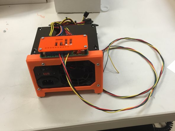
The ATX power supply is used for supplying the +5V and +12 V for the FirePick Delta electronics. However, the ATX power connector is not very convenient for accessing these voltages. Therefore, a frame was designed which mounts to an ATX power supply that provides a place to mount a break out board that allows easy access to the power lines. By plugging the ATX connector into the back of the break out board, the voltages are now available through simple screw connectors.
Tools
Parts
No parts specified.
-
-
4 3X25 mm pan head screws
-
4 6X32 pan head machine screws to attach assembly to power supply
-
4 M3 nuts for 3X25 mm screws above
-
1 PC04 ATX cover plate with TinWhiskers logo on it (orange)
-
1 EPWR01 power supply breakout board
-
1 3D0053 ATX power supply frame. Everythng gets mounted on this.
-
4 4mmID X 14mm long standoffs
-
ATX power supply
-
-
-
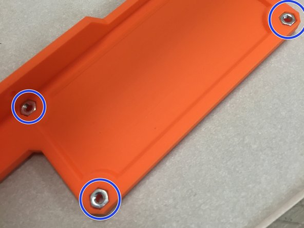
Insert the four M3 nuts into the frame nut traps.
-
These nuts will receive the 3X25 mm screws that hold the break out board and cover to the frame.
-
-
-
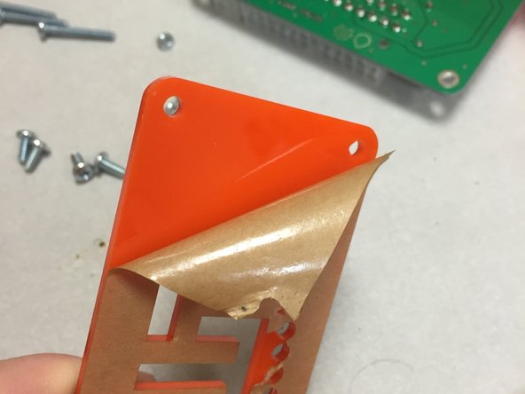
Peel off the acrylic cover from both sides of the PC02 plate.
-
-
-
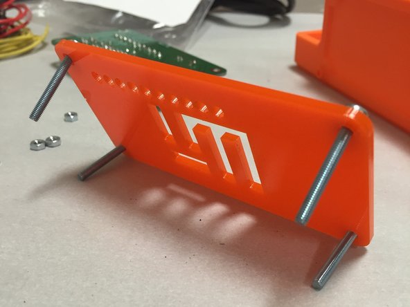
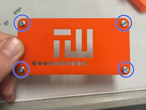
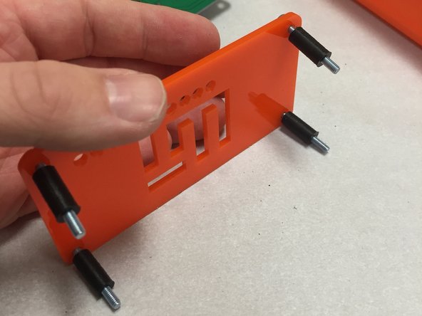
Put the M3 screws through the acrylic plate, noting the orientation in the pictures to the left.
-
-
-
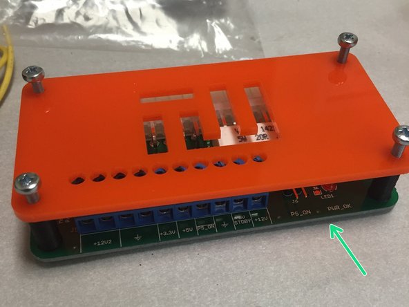
Add EPWR02 breakout board as shown. Note orientation.
-
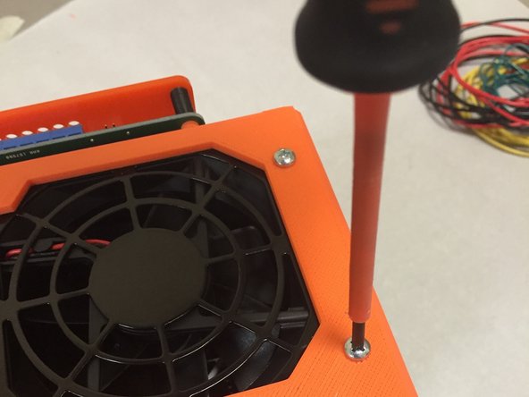
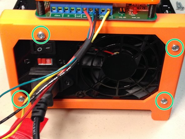
Screw this into the plastic frame housing.
-
-
-
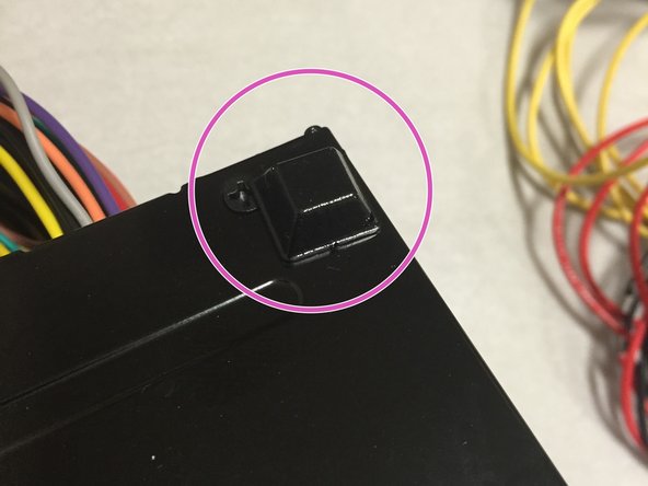
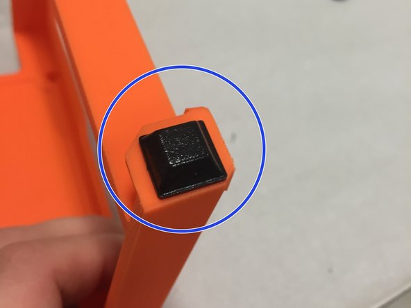
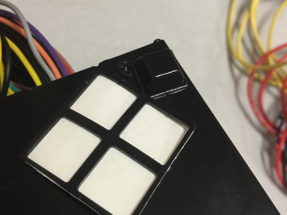
Add rubber feet to the four corners of the power supply as shown.
-
Two on the front orange frame
-
Two on the rear corners of the power supply
-
You may want to rub alcohol onto the area before applying the rubber feet. If there is any grease or dirt, they might not stick for very long.
-
-
-
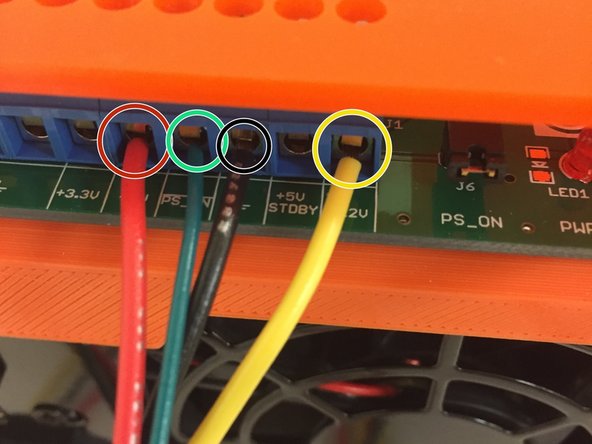
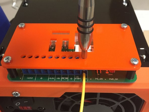
Add wires to the screw terminals.
-
RED: +5V power
-
YELLOW: +12V power
-
BLACK: Ground
-
GREEN: PS_ON
-
-
-
Set the power supply aside, and work on the other modules. When done, the power supply wiring will connect to the EMC02 motion controller board.
-
Cancel: I did not complete this guide.
7 other people completed this guide.


