
-
-
Route the stepper motor wires and the hotend wires as shown. The wires should exit "up" towards where it would plug into the EMC02 motion controller board.
-
Use cable ties to hold the wires against the motor so that they don't rub on the Wade extruder large herringbone gear.
-
-
-
Route the wires to the EAT0004 module.
-
Note: We'll define which wires go to which terminal block positions in the next step.
-
-
-
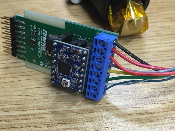
Insert wires into the terminal block of the EAT0004 as shown.
-
Pin 1 and 2: Pin 1 goes to the hotend's black wire. Pin 2 goes to the hotend's red wire.
-
Pin 3: Stepper motor red wire
-
Pin 4: Stepper motor gray wire
-
Pin 5: Stepper motor yellow wire
-
Pin 6: Stepper motor green wire
-
Pin 7 and 8: Thermistor (twisted pair, color varies). NOTE: The thermistor doesn't have polarity, you may connect either pin as necessary.
-
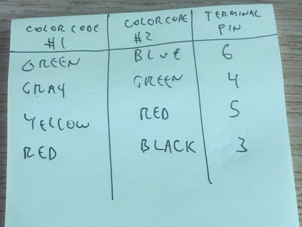
NOTE: Some of the stepper motors had a different wire color coding. If your cables have the colors blue, green, red, and black, please use the cross-reference in the second picture displayed in this step.
-
-
-
Please follow all steps of the commissioning guide before using this modular tool.
-


Cancel: I did not complete this guide.
2 other people completed this guide.
