
-
-
Use the full-size PDF exploded diagram as a reference while building this assembly.
-
NOTE: Do not use the Dozuki thumbnail.. use the PDF linked above.
-
-
-
Place the PCB heated bed plate (red) on the work surface, with the LED and resistor facing UP.
-
Place the powder-coated steel bed plate (black) on top of the PCB, and line up the four holes. Make sure that the four countersunk / beveled holes are facing UP.
-
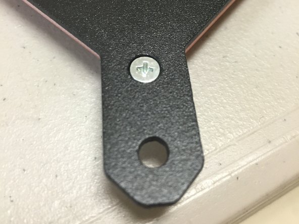
Place a flat-head M3 x 8mm screw through the steel plate, and through the PCB. Make sure that the head sits completely FLUSH with the bed plate.
-
Carefully pick up the two plates while keeping the holes aligned. Place an M3 washer on the back side of the PCB, onto the M3 screw thread.
-
Screw an M3 nut onto the screw thread, to secure the pieces above.
-
-
-
Ensure the screw heads are flat against the steel plate surface. Use your fingers to feel for any bumps.
-
-
-
TBD. The thermistor gets wired exactly the same as the hotend thermistor (with the ferrules, heat shrink, etc). I will try to duplicate this material here, when time allows.
-
-
-
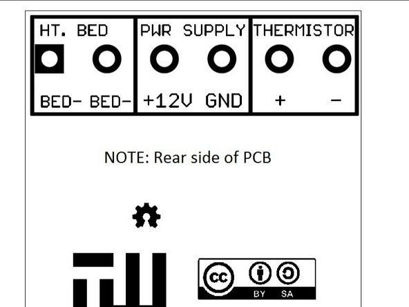
Observe the power connection table, that you will find on the PCB heated bed.
-
We will be wiring the machine for 12 volts. Note that pins 2 and 3 must be connected together to GND.
-
-
-
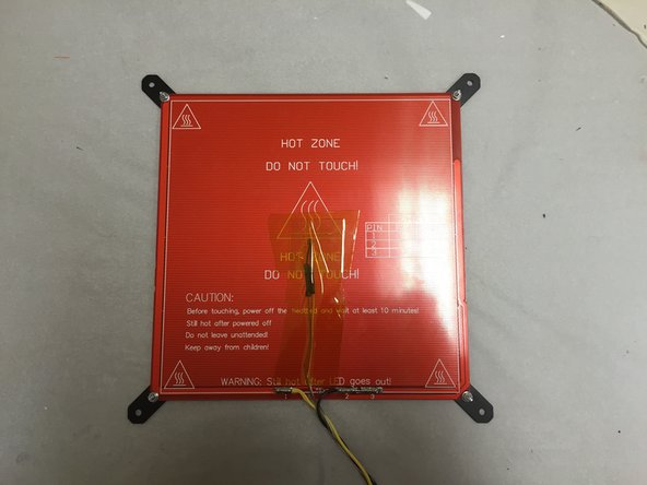
Use Kapton tape to secure the thermistor to the heated bed PCB, as shown.
-
Run the wires towards the side of the PCB heated bed with the bed electrical connections and the LED / resistor.
-
Secure the wires all the way to the edge with the tape (not just at the center)
-
Note that Kapton tape is not included in the beta kits, as the rolls are quite expensive and hard to buy in bulk. Not to mention that so little of it is actually used in the machine. This is one item that most tech guys should have in their toolbox, so buy a roll if you don't already have one.
-
-
-
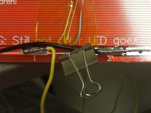
Solder the black 30" (~760mm) 18 AWG wire to pins 2 and 3. (Make sure that you didn't grab the black 50" wire.. Both are included but you need the shorter one for this step.
-
Solder the Yellow 30" (~760mm) 18 AWG wire to pin 1.
-
You may use the included clamps to hold the wires while soldering, as shown.
-
Make sure to use enough solder on these connections to make a very good connection. There will be ~10 amps of current in this circuit, so make sure to use plenty.
-
-
-
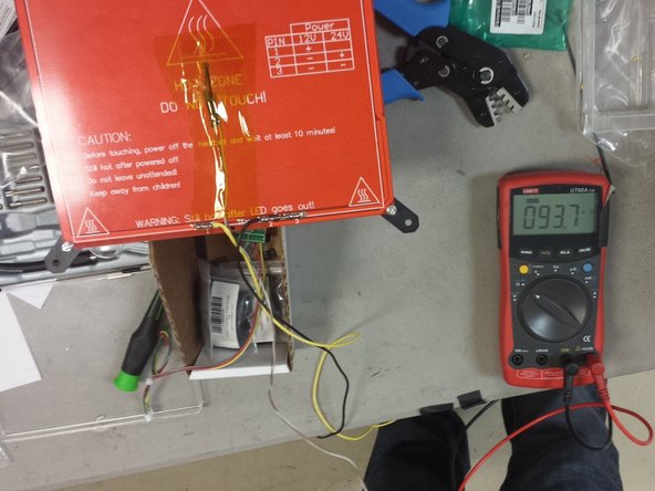
Use an ohm meter to measure the resistance of the heated bed.
-
The resistance measured should be 1.5 ohms, at most.
-
-
-
Use an ohm meter to measure the resistance of the thermistor.
-
The resistance measured should be 100K ohms, +/- 20K ohms (really depends on exact temperature in the room)
-
-
-
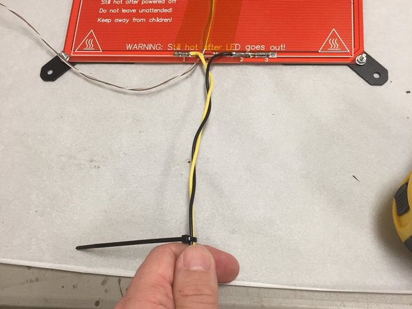
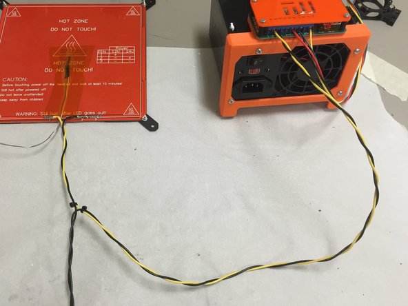
Tightly twist yellow & black wires for 5-6"
-
Place a zip tie at this point, around these two wires.
-
-
-
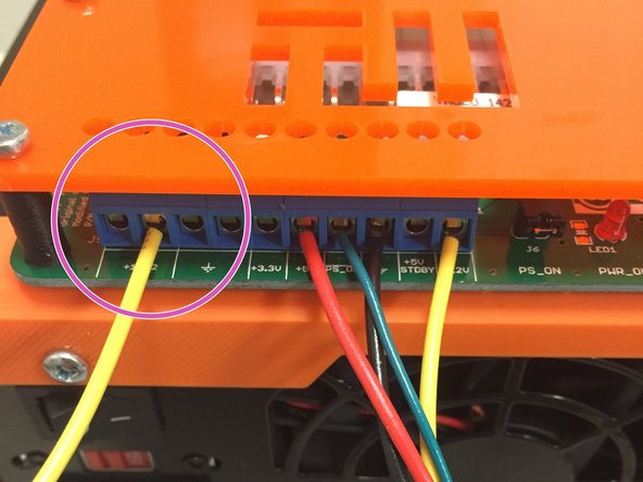
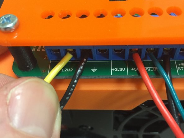
Plug the yellow wire into ATX power supply terminal strip, as shown in the picture. Tighten the screw until the wire is secured.
-
Plug it into the EXACT terminal shown. It must go to the '+12V2' terminal.
-
-
-
Plug the longer 50" wire into the power supply.
-
This is the OTHER piece of wire from the kit! Not the black wire that's connected to the PCB. DON'T connect the PCB black wire to the power supply, because that will cause the bed to be constantly on which is UNSAFE!
-
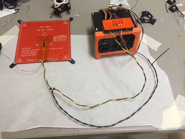
Twist this longer wire with the yellow wire, until it reaches the bed's black wire.
-
Twist the two black wires together (the one from the PCB and the one from the power supply, which should make the wires form a "Y". Twist them until the very end, and then place a zip tie to keep them from unraveling.
-
-
-
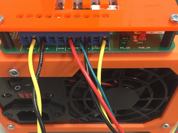
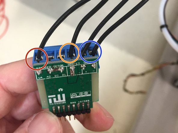
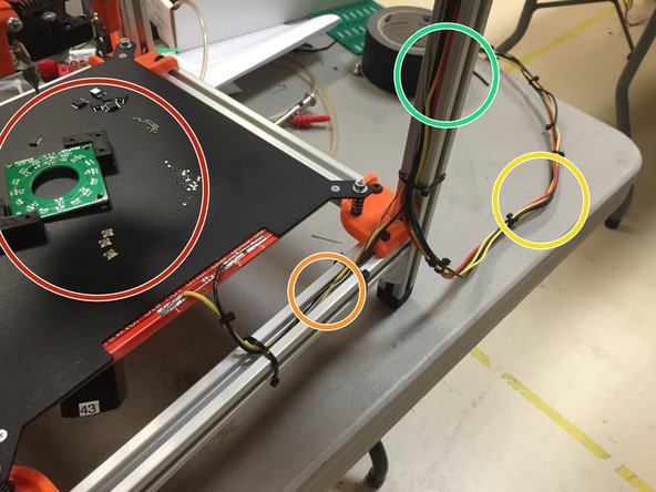
Screw the 18 AWG black wire from the heated bed PCB into the terminal circled in RED.
-
Screw the 18 AWG black wire from the ATX power supply into the terminal circled in ORANGE.
-
Connect the thermistor wiring to the two terminals shown in BLUE.
-
Note that the thermistor is not polarity sensitive.
-
Note that the PCB and ATX power supply connections, however, are polarity sensitive, and must be connected as shown. You may need to use a multimeter in continuity mode since the twisted wires are the same color.
-
NOTE: The thermistor wiring (the twisted cable) is very thin and may not be able to be screwed into the terminal strip. If this is the case, use a spare piece of 18 AWG wire
-
Note that the silkscreen was incorrect on the PCB production run. Please use the one shown in the second image, which is correct. Our apologies for missing this before we placed the order.
-
-
-
Attach the 3D0052 heated bed brackets to the frame, if you haven't already.
-
Place the M4 nuts into the nut traps in the heated bed brackets.
-
Place an M4 washer on the top center of the heated bed bracket, over the M4 hole.
-
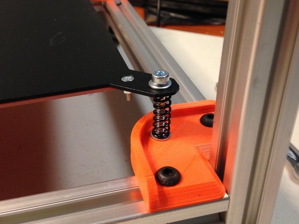
Place M4 x 30mm L socket head cap screws through the heated bed plate corner holes, placing a washer below each screw head, and also on the bottom side of the steel plate.
-
Carefully position the four springs at each corner, as shown in the picture, sandwiched between the steel bed plate and the 3D0052 bed brackets.
-
Note that the glass and clips are not needed at this time. They are not needed for SMT pick-and-place, and are only needed for 3D printing usage.
-
-
-
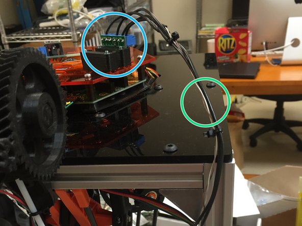
Zip tie the cable to the frame as shown.
-
Heated Bed
-
Thermistor wire, 30" yellow wire and 30" black wire
-
Power Supply Cable - 30" yellow wire, 50" black wire (NOTE: Shown bundled with EMC02 power wires)
-
Thermistor wire, Black wires up to EAT0002
-
EAT0002 module
-
NOTE: This was an older picture, the yellow/black wires should be soldered to the BOTTOM of the heated bed, not the top as shown. Realistically it doesn't matter, but the glass is easier to install if the wires are on the bottom.
-
-
-
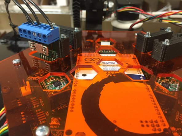
Plug into EMC02, into SLOT 1.
-
Currently with the Marlin FPD fork, it MUST be plugged into the module slot as shown.
-
-
-
Please follow the commissioning tutorial, to ensure that the heated bed is working properly.
-
Note that the commissioning tutorial isn't written yet, but it will be ready shortly. Check back soon!
-


Cancel: I did not complete this guide.
4 other people completed this guide.
