
Parts
No parts specified.
-
-
Gather all the pieces:
-
1x EMC02 motion controller board
-
PC04a EMC02 cover plate (orange acrylic)
-
3D printed pieces: 4x 3D0021 modular tool card cages, 3x 3D0015a EMC02 mounting plate, 6x 3D printed 18mm unthreaded standoffs
-
Arduino Mega 2560
-
3x stepper motor driver modules
-
Frame hardware bag: 6x M3 x 30mm L pan-head machine screws, 8x M2 x 20mm L pan-head machine screws, 14x M3 nuts
-
-
-
URL to PDF of exploded view diagram: https://drive.google.com/open?id=0B-U7ic...
-
-
-
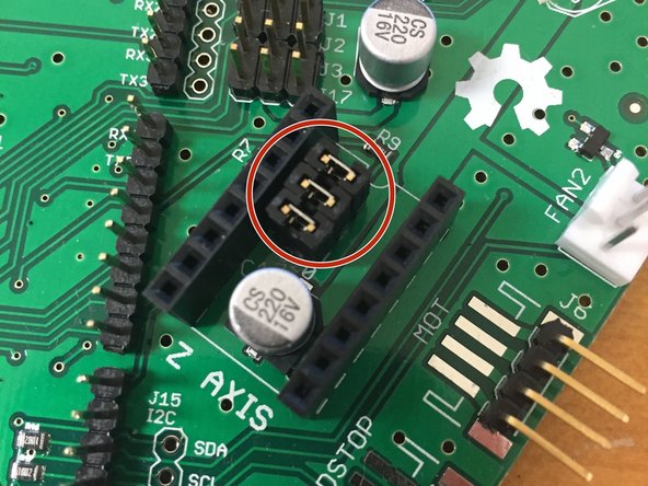
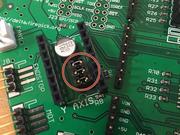
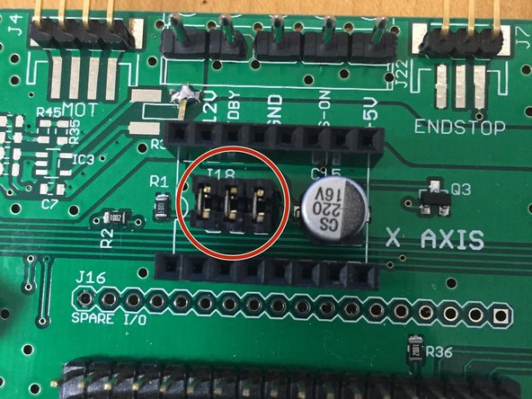
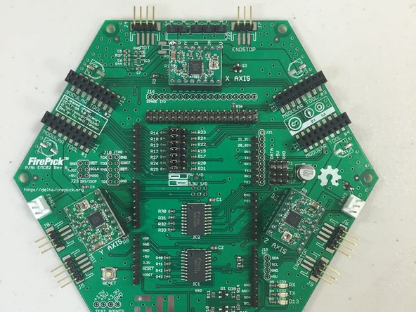
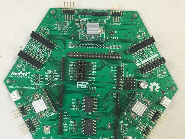
Make sure all jumpers are installed under each of the StepStick stepper driver modules. There should be three jumpers (shunts) under each module.
-
This puts the stepper motor drivers into 16x microstepping mode. Currently, the official FirePick Delta Marlin code requires the microstepping jumpers to be set as stated above.
-
-
-
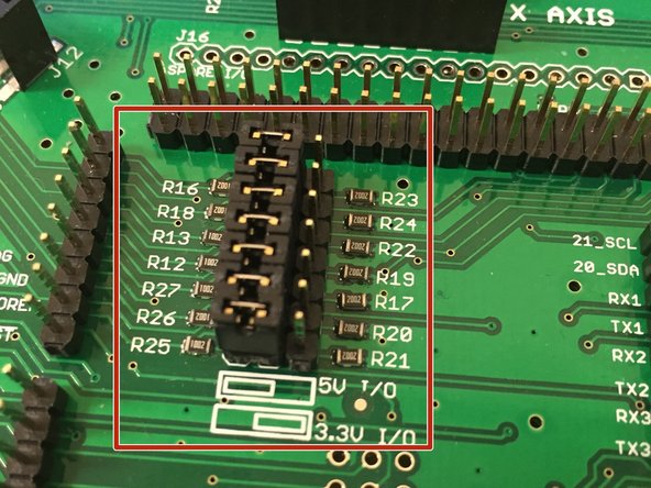
Set the voltage jumpers to '+5V'
-
NOTE: Currently the only supported microcontroller for the EMC02 is the Arduino Mega 2560, which is uses +5V for the I/O. These jumpers are provisioning for the future ability to work with +3.3V I/O microcontrollers, for example the Arduino Due and the Smoothieboard compatible (LPC1769).
-
-
-
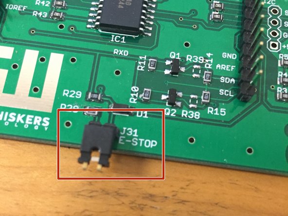
Ensure that there is a jumper / shunt on the E-Stop circuit connector (J31). The system cannot be commissioned with this jumper left un-plugged.
-
The logic for the E-stop circuit is normally closed. You may add a normally-closed pushbutton switch (the non-monemtary type) as an e-stop. We do not currently include one, but have provisioned for it to be added.
-
-
-
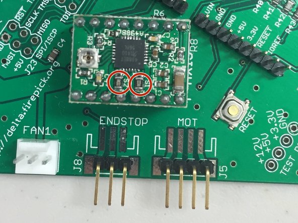
Add 3x Stepper Drivers (A4988 Stepstick), making sure to insert them with the correct orientation.
-
The orientation is as follows: The two big resistors in the middle on one side go TOWARDS the motor connector. Those are the current sense resistors, which are placed next to the four stepper pins. Use them to ensure that you're plugging your modules in correctly.
-
-
-
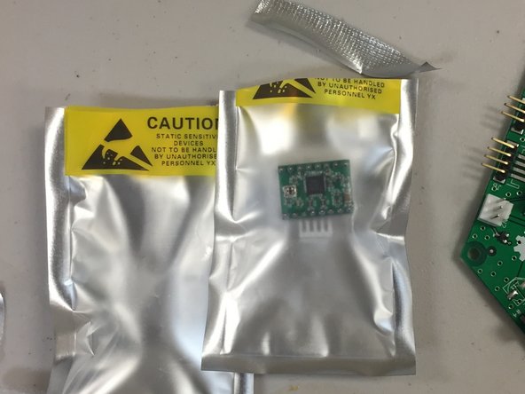
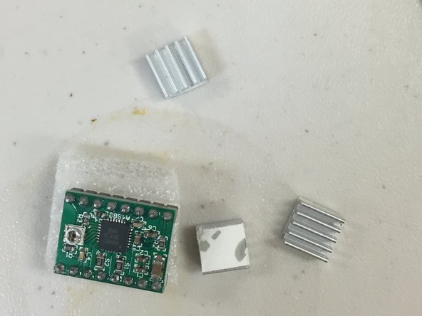
Add heatsinks onto the StepStick modules.
-
Note that these are included with the Stepsticks, in the static bag.
-
-
-
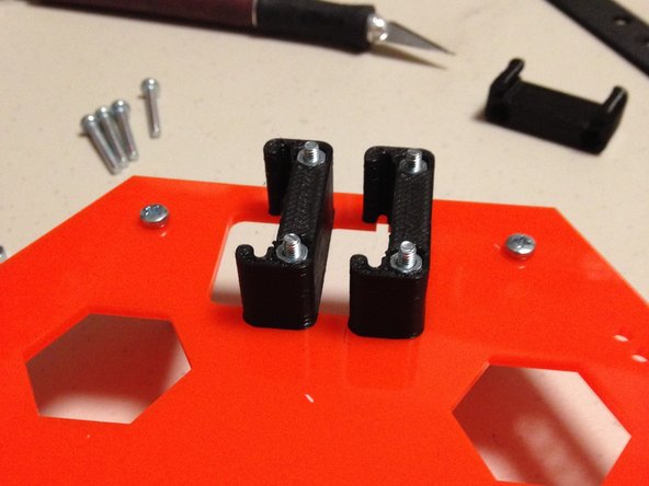
Add 3D0021 Modular tool card-cage pieces. Use the FPAN-M3-20L screws and M3 nuts (2 per card cage)
-
NOTE: The first kits went out with only three 3D0021 pieces instead of 4. We are going to send these pieces out to our customers in an errata kit (please update the google doc we sent you so that we know you need this piece!)
-
-
-
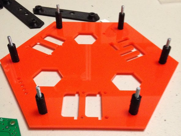
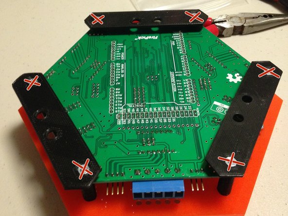
Test fit standoffs.
-
DO NOT attach at this time.
-
Note the orientation and position of the center holes in the mounting plate.
-
-
-
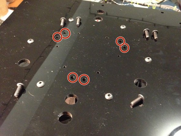
Remove six center M5 button-head cap screws from top acrylic
-
-
-
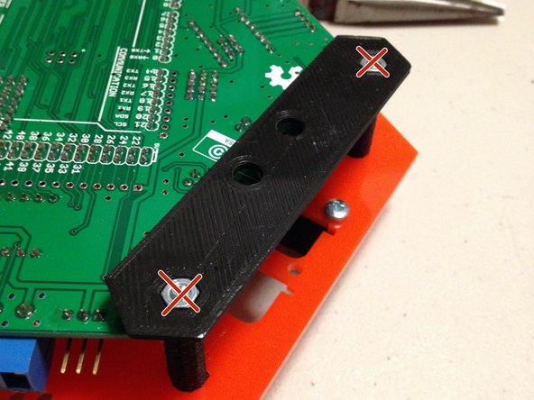
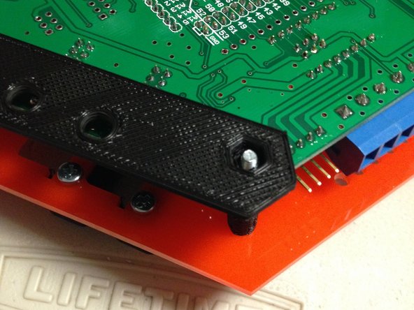
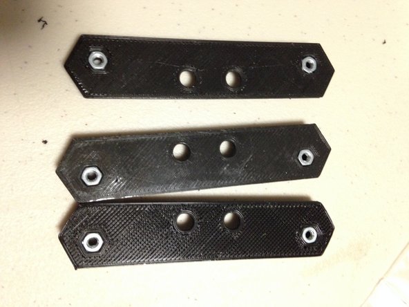
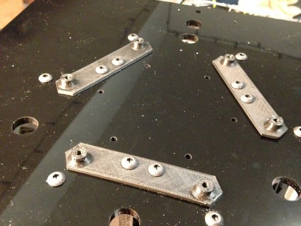
Add 3D0015a mounting plates to PC01 plate. Use M5 button-head cap screws to fasten as shown. Note the orientation of the 3D0015a pieces.
-
Test fit EMC02 to ensure holes line up before tightening bolts
-
-
-
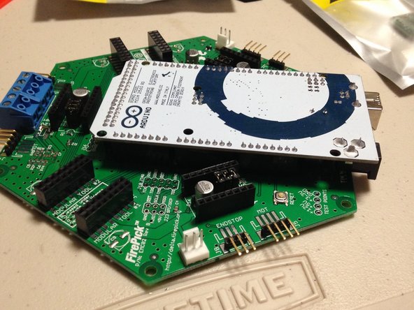
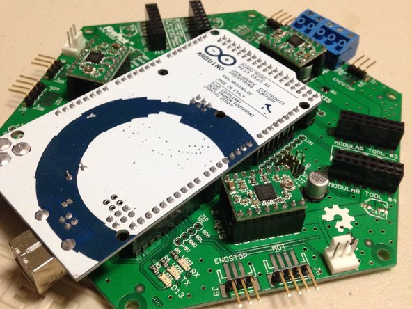
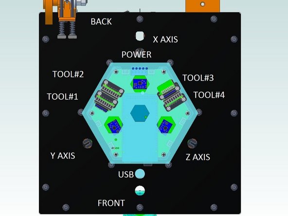
Attach EMC02 board and acrylic top to top of delta motor assembly
-
Pay special attention to orientation while placing this assembly onto the machine. Use the picture provided as a reference.
-
-
-
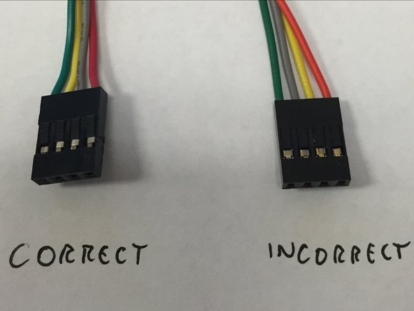
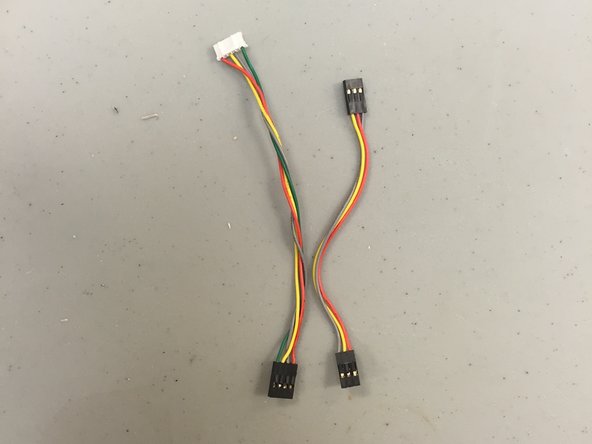
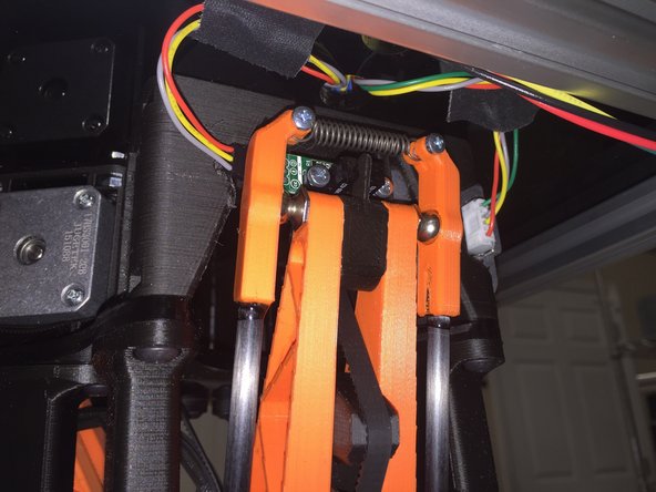
Take a second and ensure that you've got the correct connector wire order on your motor and endstop cables. We crimped these by hand, and unfortunately had a significant amount go out with the wrong pinout. Use the pictures to the left as a reference.
-
Order of the stepper motor wiring for the black housing should be:
-
1 RED
-
2 GRAY (not yellow)
-
3 YELLOW (not gray)
-
4 GREEN
-
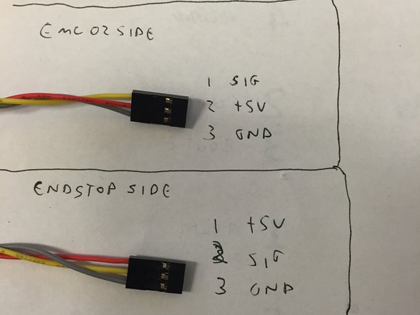
The endstop cable is not wired 1:1. There is a twist in it. and needs to match picture#3 exactly.
-
-
-
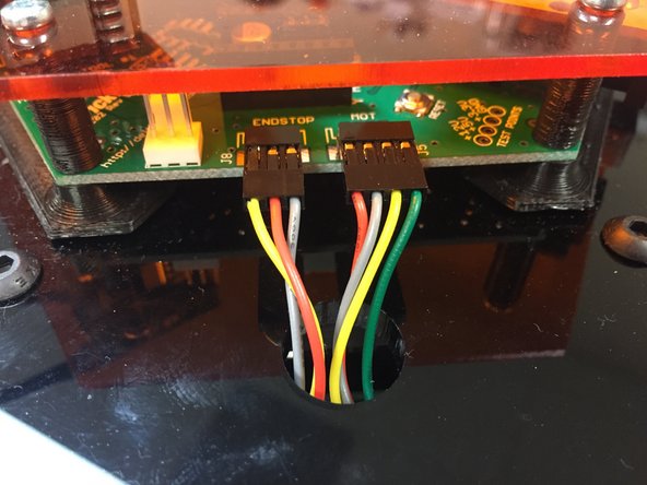
Plug cables into EMC02. Ensure that the wire color orders match the pictures exactly.
-
Do this for all three sides, for the stepper motor and the endstop cable.
-
Leave the wires hanging on the bottom. We'll connect them in the next step.
-
-
-
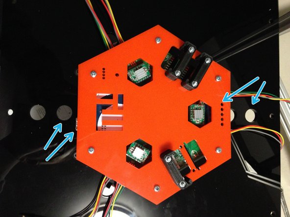
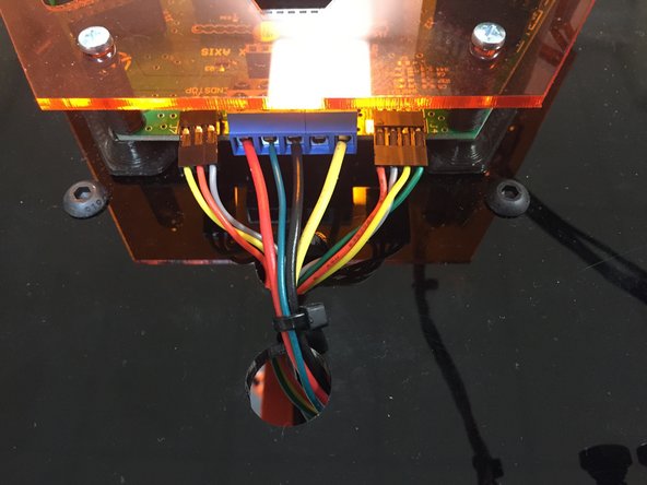
Now underneath the top plate, route the wires as shown in the picture(s). Make absolutely sure the wire color order matches the picture as shown.
-
Use duct tape or gaffer tape to manage the wire routing. It is important that these cables do not get tangled in the delta arm mechanisms.
-
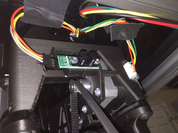
You can see above that the connector on the endstop board is on the back side of the board. This is because the delta arms "home" position interferes with this location.
-
Move the delta mechanism up to the "home" position and check for interferences. Adjust routing as needed until the arms have a clear path and nothing binds.
-
-
-
Before turning on the machine, make sure to go back and ensure all steps have been completed before starting the commissioning process.
-


Cancel: I did not complete this guide.
8 other people completed this guide.